Here’s how to enjoy the benefits of Knock Block functionality without the hassle of having to
- fit a special stem or
- install too many bits and pieces.
We’ve come up with a simple integrated headset solution to block those knocks—Patent Pending 108203231.
Everything is explained in the video. But we have also provided the details in this post if you’d prefer to read on.
NOTE that there are some details included here that are not in the video.
Knock Block means to ‘block’, or prevent, ‘knocks’ to your mountain bike downtube.
If you have a straight downtube, the tops of your forks can turn back into it … harshly. A dent in aluminum. Probably a crack in carbon.
Bye bye carbon frame.
Design success here really comes down to robustly and reliably
- limiting the angle of movement yet
- allowing enough movement
for a rider to experience no limitation to the usual range of movement when on the trail.
Less is certainly more when it comes to a knock block alternative.
What’s In the Headset?
Let’s take a detailed look at each component making up the headset.
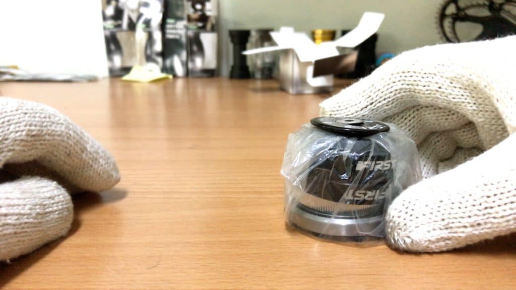
The Package
When you first meet this new headset it will be packaged as pictured.
All FIRST’s headsets are plastic wrapped with the top cap and star nut (if applicable) nestled on top.
~Check out the Headset with the built-in Spacer for fine-tuning your bike’s stack height~
Unless you are doing a fresh install, you won’t need the star nut. Unscrew the star nut from the top cap tension bolt and put it away.
A spare star nut may come in very handy even if you don’t need one for your existing fork.
Your currently installed star nut can be pushed further down inside the steerer should it pose problems. A new one can be installed where the old one was positioned.
So, keep that star nut where you can find it.
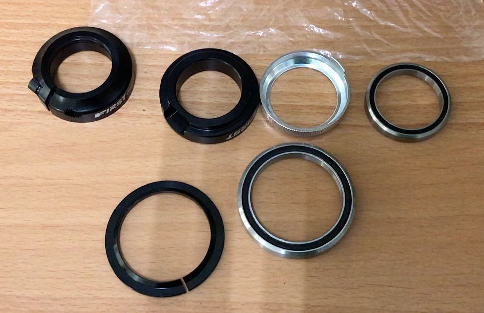
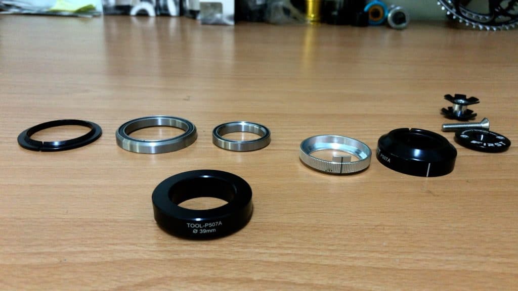
From left to right.
The knock block alternative dust cover differs from standard integrated headsets in two ways.
Firstly the rear bolt.
This functions to hold the dust cover firmly over the parts installed underneath (bearing cup and bearing … more on that in sec …).
A top cap is installed just as with any similar headset. Remember the top cap “pulls” the whole headset assemblage together
~ INTEGRIERT—Everything You Want to Know—(Installation, Removal …) ~
But the bolt ensures the dust cover will not rotate, even slightly, when under pressure. What pressure …?
… the pressure from the next part (3rd from left).
This cup sits inside the headset integrated cup. The boss, visible there at 1 o’clock (we’ll have a closer look in a jiffy), fits up inside the dustcover.
The piece in between these two (2nd from left) is the tool that assists pressing the cup into the top of the headset. On the far right we have the top (sealed) bearing.
Below is the crown race and the crown race bearing. Neither is strictly a part of this angle-limiting setup so you could have any dimension you want.
The Bearing Cup
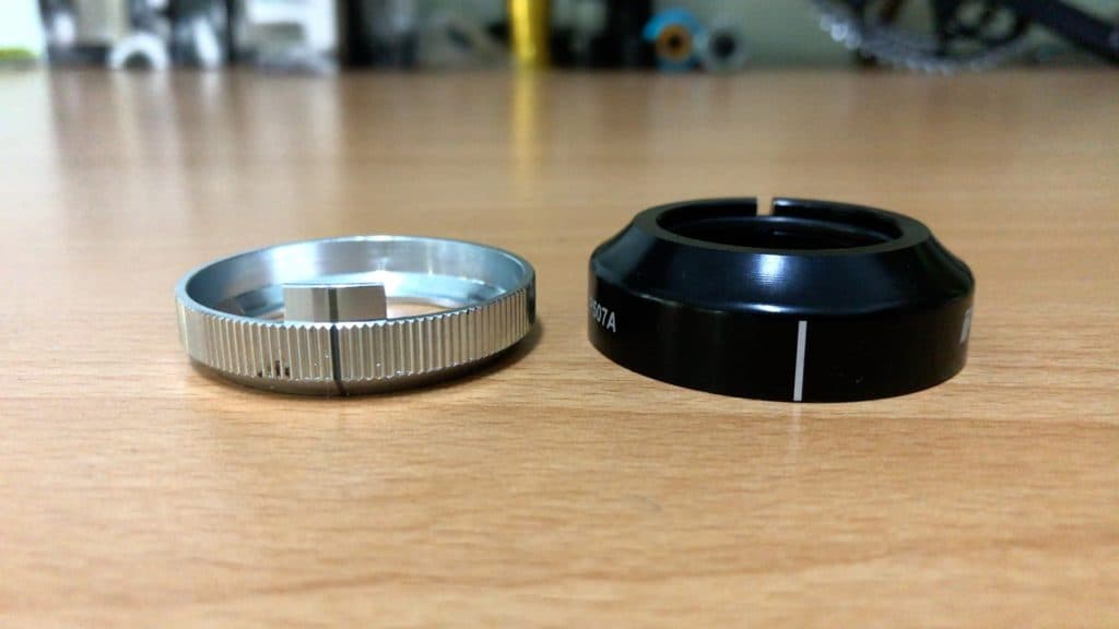
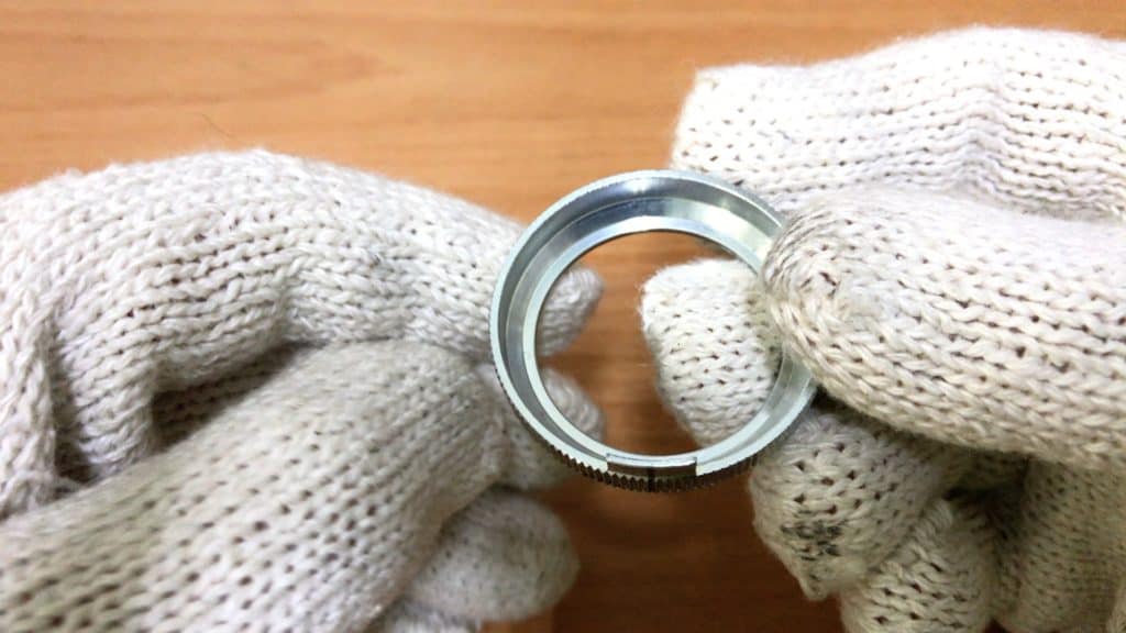
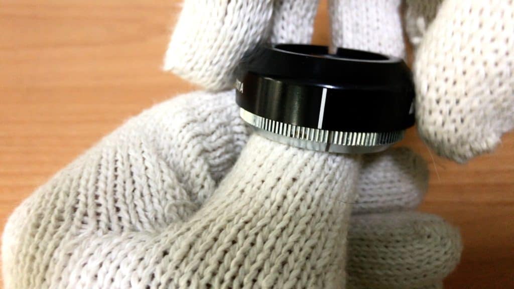
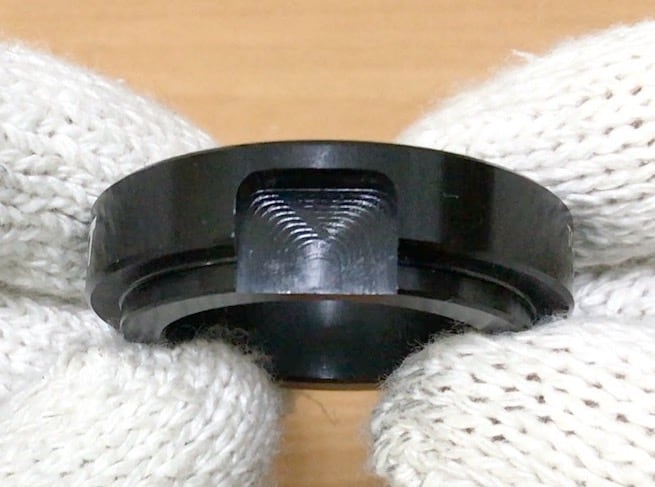
Let’s have a closer look at the bearing cup and the dustcover. They are the key components of this system.
The boss on the bearing cup (right) fits into a machined groove inside the dustcover (left).
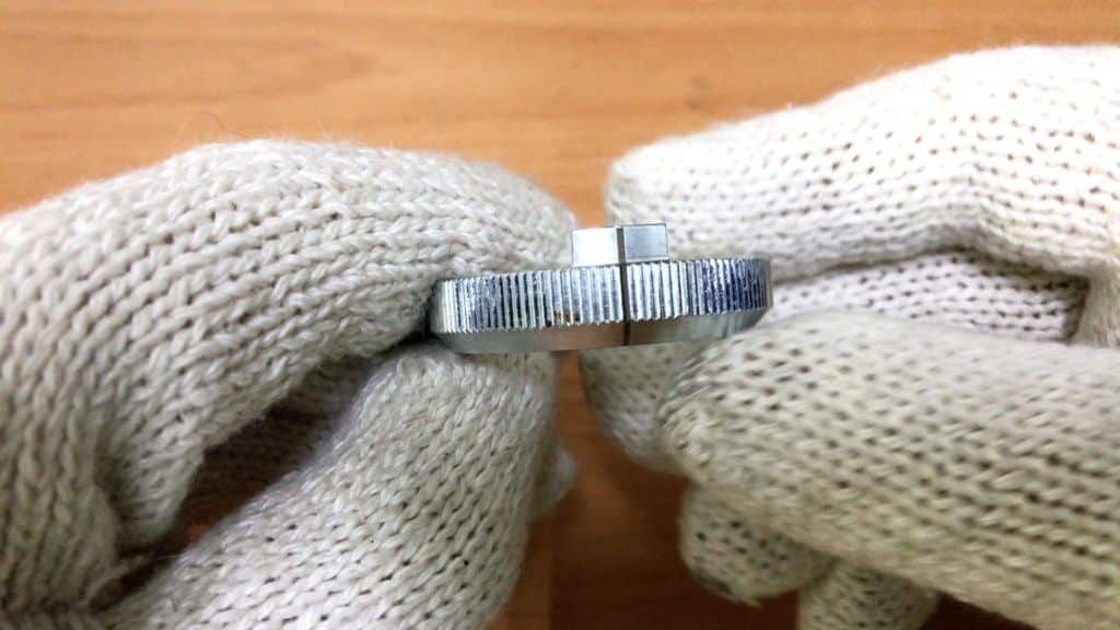
A close-up look at the bearing cup with the boss.
The lower edge is 45° and fits directly into the headtube’s integrated cup.
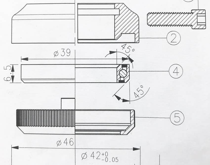
The specific dimensions in detail. On the diagram, “2” is the dustcover; “5” is the bearing cup. (The bearing is #4).
The centerline should line up as closely to the headtube’s center … imagine a line perfectly bisecting the headtube looking straight-on at the front.
You can see the centerline in the diagram dividing each part.
The cup’s outer circumference serrations hold the cup firmly in the headtube’s cup. The boss will be subject to hard impacts during its lifetime, potentially causing the cup to shift each time.
An exact fit to the headtube cup together with the serrations ensures it does not move.
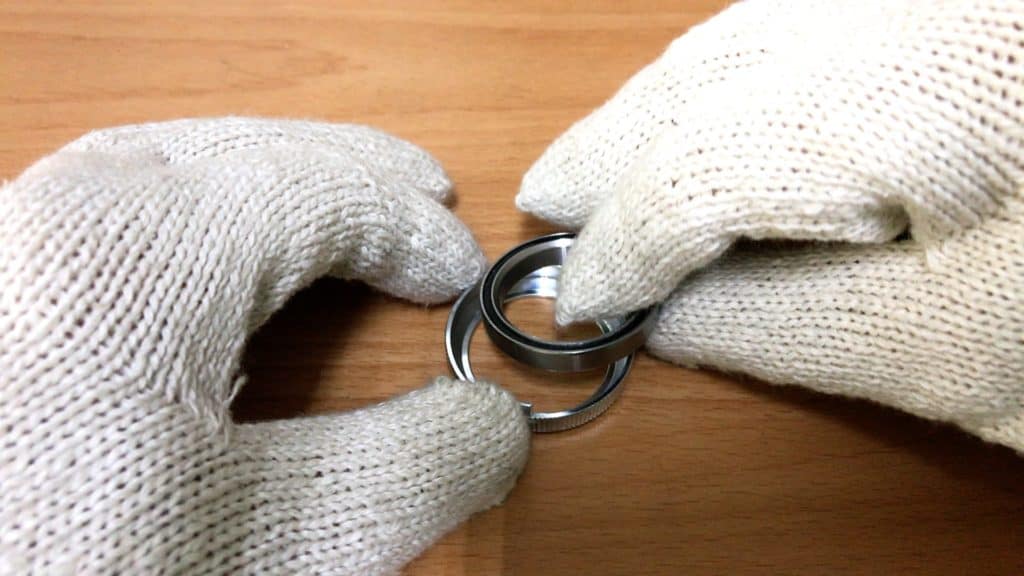
The cup’s design mirrors the headtube cup design. The bearing slots snugly into it.
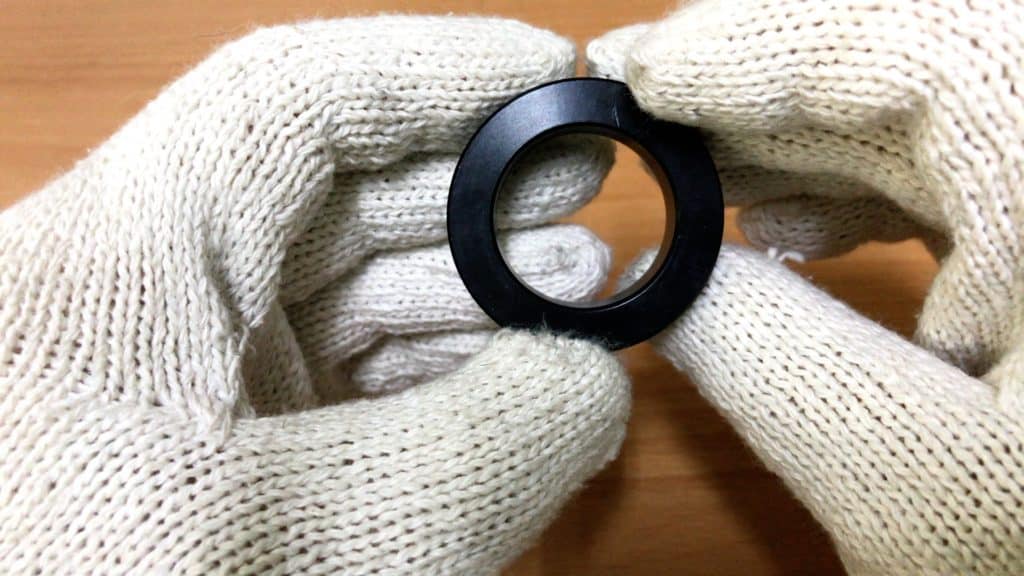
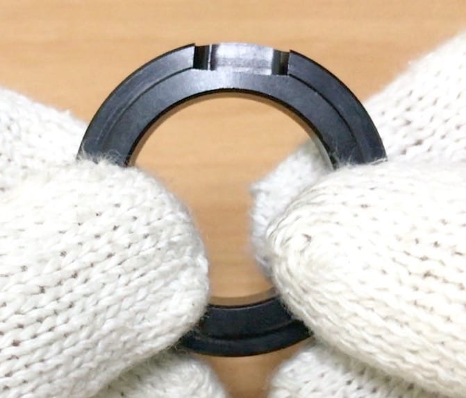
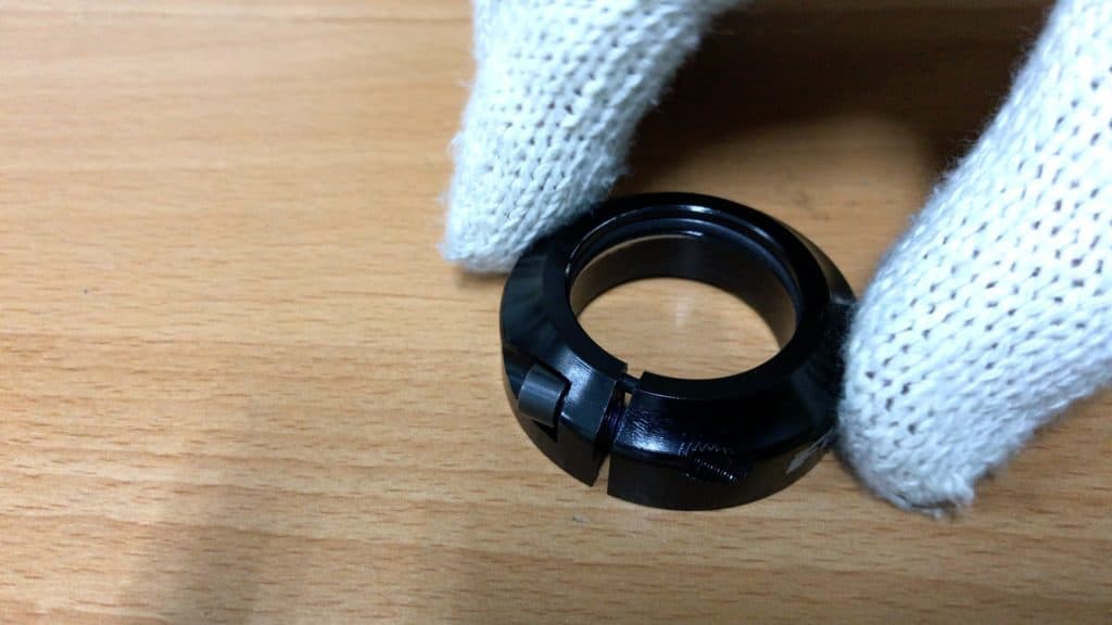
The Dustcover
The other indispensable piece—the dustcover with the groove that accepts the cup’s boss.
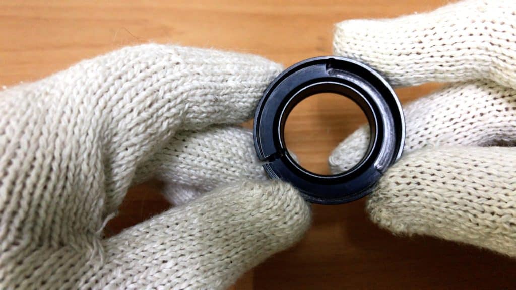
An imaginary line running from the gap at the back bisects the groove. There is 65° of turn available to the left and right. 130° in total.
When you have installed the bearing cup into the headtube, the dust cover aligns with the cup. Just line ‘em up.
As long as the bearing cup is installed at the right angle, the angle limit will be exactly the same on both sides—65°.
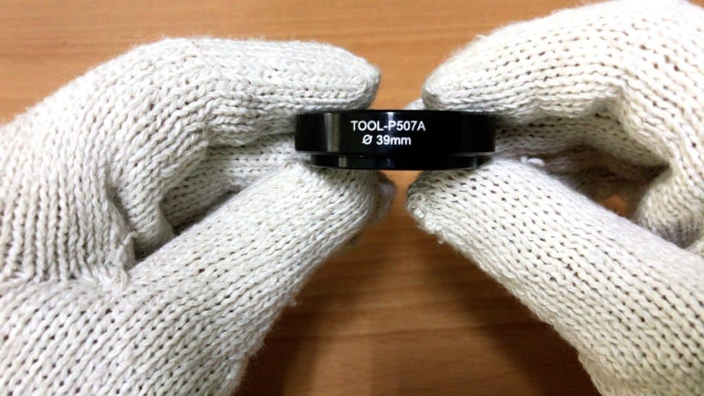
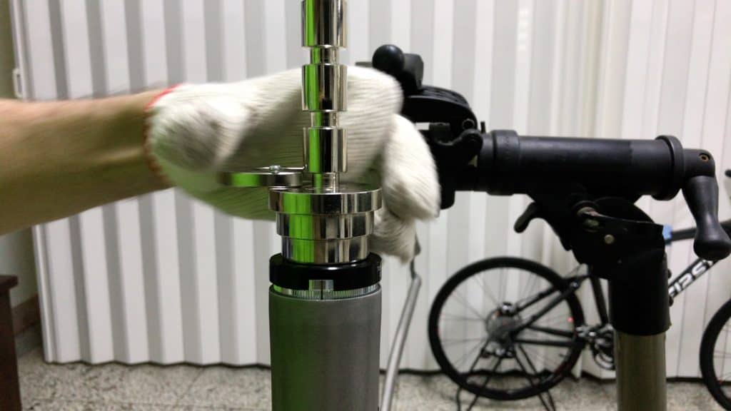
The tool enables you to press the bearing cup into the headtube. Okay … you might use a hammer to bang it in, although we would not advise this.
Far better to use the right tool to exert gentle pressure—very gentle pressure is all you need—on insertion.
The tool’s upper surface is perfectly flat. It fits flush with a headset cup press tool and makes for super-easy installation.
The gap up the top accepts the boss. The bearing cup fits snugly into the tool here.
The tool can rotate slightly from side to side—the boss’s fit into the slot is not exact, as it does not need to be.
The key point is for the bearing cup to be centered exactly within the headtube. The tool only assists installing the cup. You just have to make sure you have it positioned correctly.

The tool fits over the cup; the cup’s upper lip slots in exactly with the tool’s edge.
So there you have the headset kit.
The relationships that make this knock block design work are between:
- the bearing cup
- the dustcap
These two components are the heart of this simple setup — we’ll show how they work together in the rest of this post.
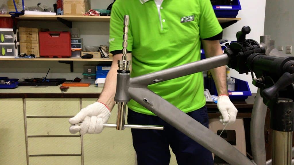
The bearing cup’s installation is key to everything. So let’s take a look at the best method to get it seated in the headtube.
Installing the Bearing Cup
A headset cup press tool is what you need. Be aware that this tool is cumbersome and takes a little getting used to.
So if you purchase this new knock blocking headset from a bike shop, get him or her to install it for you.
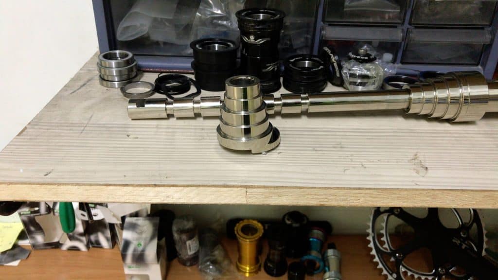
A headset cup press tool is for pressing bearing cups for threadless headsets.
Our use of it here is novel since the whole idea of an integrated headset is that the bearings seat directly into the cups built into the headtube. That’s still the case here, except for the addition of an extra bearing cup.
The tapered ends are designed to accept almost every size of cup.
Slide one cup into position at the top—that end is fixed to the shaft. Place the other cup on the other piece. I’ll just summarize here … we’ll get into the details of how we use it to install the particular bearing cup here in a sec.
You insert the shaft through the headtube—the tool compresses the cups into the headtube, top and bottom as you turn the handles.
Note that considerable pressure must be exerted to fully seat the cups the required several centimeters inside the headtube.
The bearing cup we are installing here doesn’t need that degree of force though. The headset cup just needs to be seated a few millimeters into the (already) integrated cup. Not far at all.
The first step: slot the tool and the bearing cup together.
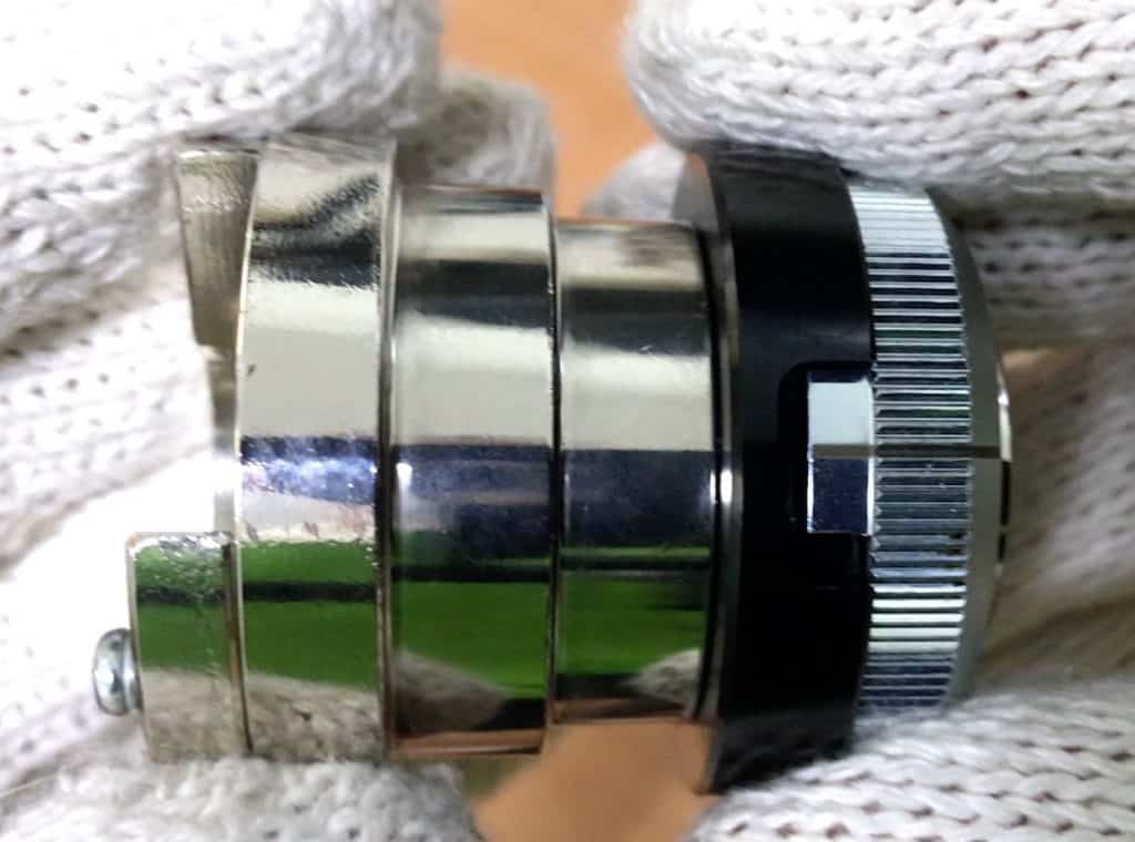
Then place the combined tool and cup on the headset press’s locking end. In this case the press cup’s smallest step is just right.
Then position the press-cup-with-headset-tool so the bearing cup to be installed is sitting square inside the headtube lip a fraction of a millimeter.
If you were performing a standard headtube cup install, this piece would be fitted at the bottom, fitted upwards into the headtube. The shaft along with the other cup would be inserted from the top.
For this particular situation, an upside-down solution works.
Insert the shaft to the nearest detent. Slide the lock-piece across. Tighten the lock-piece’s locking hex bolt.
You’ll find the whole assemblage is a little sloppy, which is perfectly normal. Just turn the handle to take up the slack and you are ready to install the bearing cup.
Saying again for emphasis. This line must be centered on the headtube’s center within a degree. One degree of tolerance is barely tolerable, though. Once you press in the bearing cup, there’s no going back to adjust the angle. Getting the line dead center takes a little patience.
Correctly installed, you’ll get the full 65° on each side (65°-65°130°), not, say, 63°-67°! Or something like that.
Very gentle pressure C/O a slight turn of the handle does the job.
The headset press cup evenly presses the bearing cup into the headset’s integrated bearing cup.
Success!
Remove the tool to complete the installation (bearing and dustcover).
Release the pressure, turn the handle enough to loosen up the headset cup press tool’s press cup. Slide the locking-catch back across and slide all pieces free of the headtube.
Install Bearing & Dustcover
You should have the bearing cup sitting in the headtube’s integrated cup.
The cup should be sitting evenly in the cup. Perfect positioning will happen automatically as long as you use the headset cup press tool correctly.
You can now seat the bearing into the freshly installed cup.
Coating a smear of grease in the cup and around the bearing is advised.
The tolerances machined into this product are extremely precise. But there is always going to be slight movement during use. Grease is insurance against creaking.
Creaking can drive many riders batty. Cases where mild, sensitive riders with super-high EQs have been turned into raving beasts by persistent squeaks and creaks are documented …! Quite apart from being driven mad, you don’t want to increase the places where creaking can occur. Finding the source of other creaking components (you’ll definitely have this issue sooner or later) becomes that much harder.
Many bike shops advise slapping plenty of grease on. A lot of grease repels water, providing great protection for your bearing which is not a bad thing, even though the bearing is sealed and already well protected from the elements..
The more grease though, the more dirt that piles up over time. A light smear insulates against water and creaking.
The fork can now be installed.
Once the fork is sitting snugly up against the crown bearing down below, the dustcover can go on.
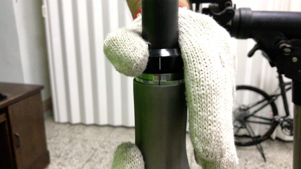
You will find this unit’s dustcover fits very snugly around the steerer. Enough to almost hold a heavy fork in most cases—only minimal support is necessary. But take care that the fork does not drop out all the same.
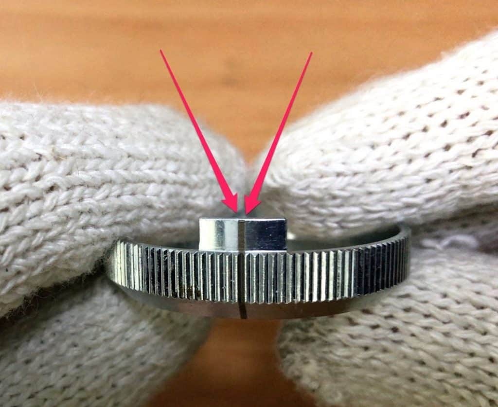
Push the cover down over the top of the cup and bearing.
Match the line on the bearing cup boss with the line on the cup. Providing you have installed the cup accurately, aligning these marks ensures 65° of rotation to the right and left.
Re-Install Stem
Tighten the dustcover bolt. 3nM torque setting should be fine. Maximum 5nM.
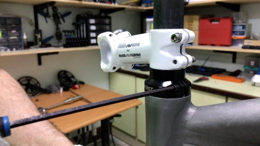
Install the stem.
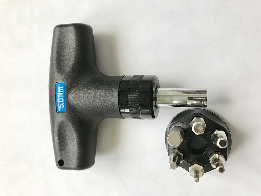
As an aside, a preset torque tool such as this one from Synpowell for the home workshop is handy for a job like this. You are limited to 5nM for a tool like this. But 5nM is a reliable setting and, besides, measuring beats guessing. Nothing beats a torque wrench with a range 0-25 or 30nM though.
For the demo here, we are not cutting the steerer so won’t be showing the top cap installed and tightened. Nothing out-of-the-ordinary with the top cap here anyway.
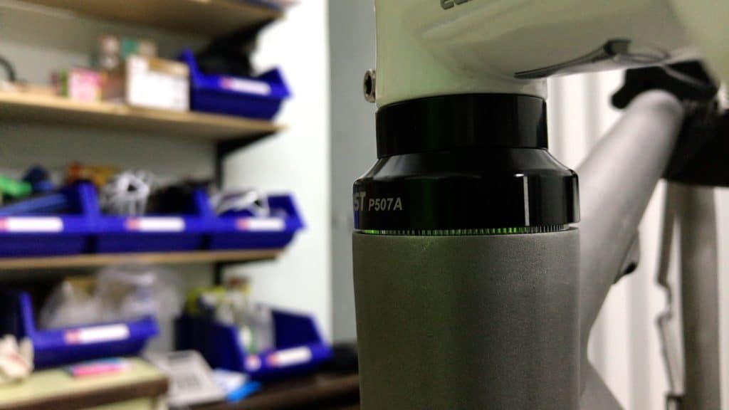
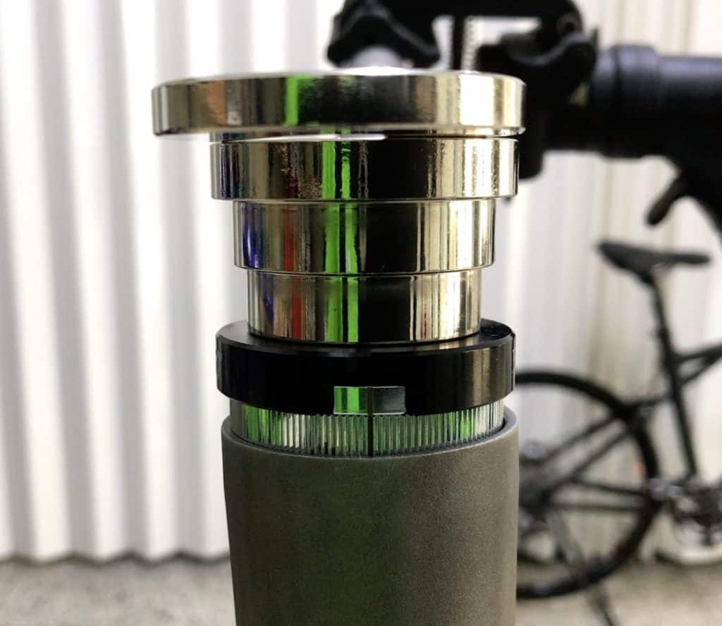
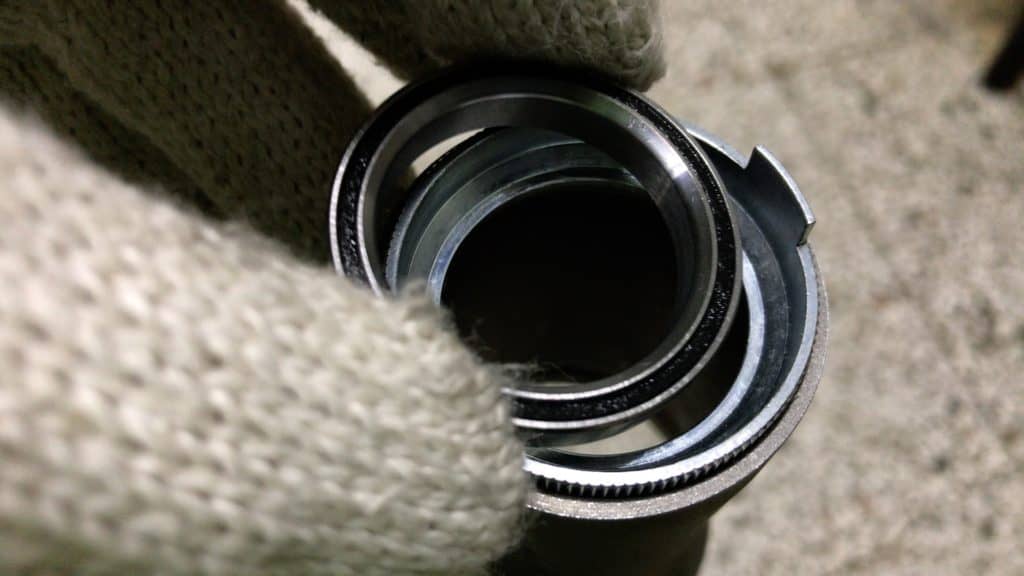
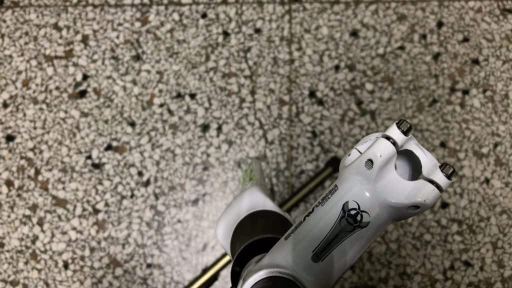
When completely installed and operational, this is what you will see.
A slight gap where the dustcover sits against the newly installed bearing cup.
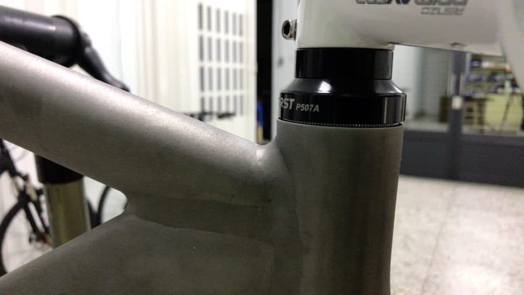
The fork is rotated to the right, at the complete limit of 65°, the line indicating the center position of the bearing cup, technically zero degrees if you’ve installed it accurately.
The line has no particular function here. Just remember that the line must match the bearing cup boss’ line.
65° to the left.
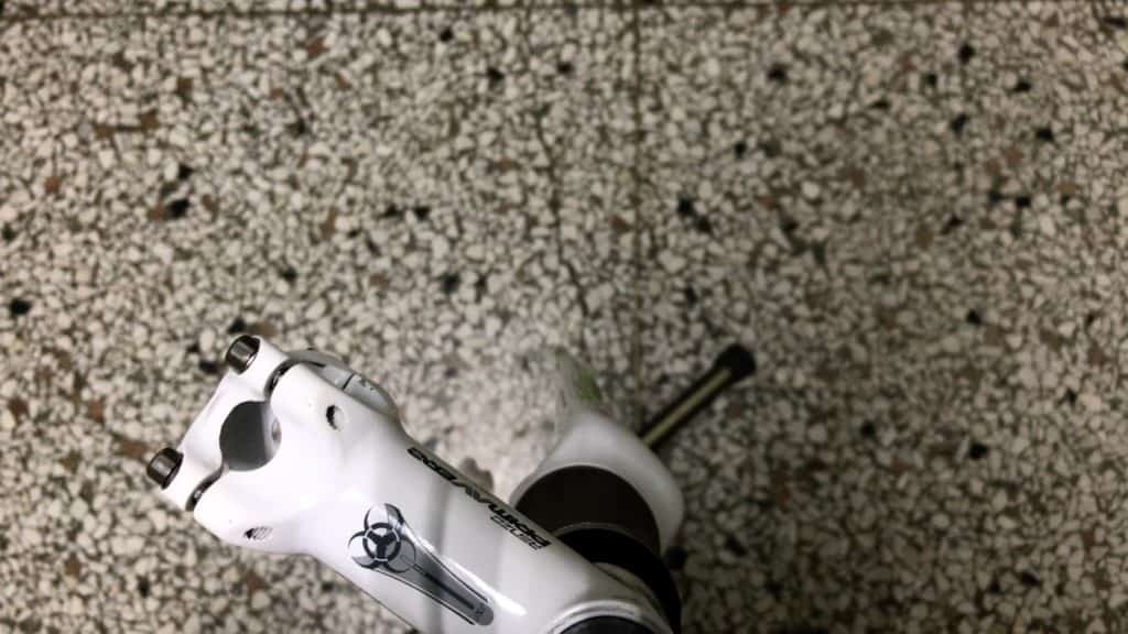
The view from the top when turned to the left.
Didn’t have a mountain bike fork available for this demo so a road bike fork was used. The only difference is that the fork would not impact the downtube. All the techniques and principles covered here apply in equal measure.
The view from the top when turned to the right.
So there you have the lastest design.
Let us know what you think in the comments below.