I cover in detail key steps to take in building a bike, whether you:
- assemble a bike from scratch
- cobble together a bike from broken down bits of other bikes
You’ll also learn which tools are essential, and which are desirable, depending on how seriously you want to get into building bikes.
There are also many tips along the way, little things that if you don’t get right will cause big problems.
Having learnt how to properly assemble a bike, if you are thinking of ordering a bike online, which will likely require basic assembling, you’ll find the task of putting it together much easier.
Although there is a lot of variation in the way components are designed for every part of a bike, the techniques I cover apply to all of the main categories.
The essential requirement for building a bike, though, is patience.
Patience in league with practice, because fitting components to a frame without damaging either frame or component is about developing the right touch.
If you’re just starting out, you just have to take it slow in order to develop that touch. Moving through the build reflectively armed with a guide like this, you’ll put together a bike safely.
Assembly Order of Components:
1. Bike Stand & Frame
2. Bottom Bracket
3. Crankset
4. Front and Rear Derailleurs; Rear Wheel
5. Chain
6. Fork, Stem, Headset, & Front Brake
7. Handlebars, Shifters, Cable Housing, & Cables
8. Bar Tape or Grips
9. Seat post and Saddle
10. Tighten Bolts to Torque Tolerance and Cut Cables
USEFUL PRELIMINARY STEPS in BUILDING a BIKE
The order in which parts are assembled differs amongst professionals. Rigorous sequences only apply on mass assembly lines for the sake of efficiency.
As I explain and illustrate each part of the approach taken here, I’ll give the reasons for each step and suggest what you might do differently and why.
Essential Tools
Here are several tools you should have for building a bike.
Allen Wrench Set
A good quality Allen wrench set will last you forever.
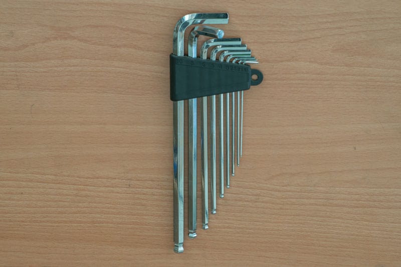
German or Japanese manufactured Allen wrenches are the best as they keep their edge: over time the six edges of an Allen wrench’s hexagon.
You need a range from 2mm through to 1cm.
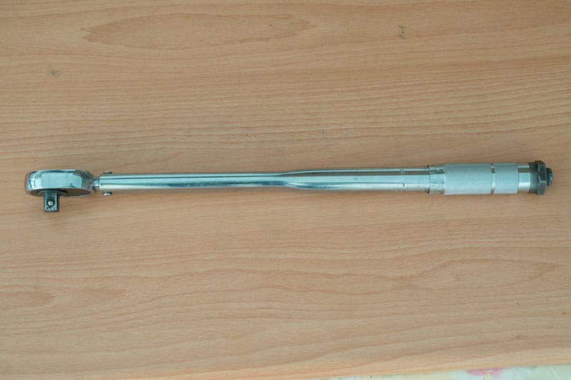
Torque Wrenches
You should have two torque wrenches: one for the bottom bracket, one for all other bolts. The first is optional; the second, essential.
Using a torque wrench means you don’t have to worry about the tightness of the various bolts required to fix bike components into position.
If a bolt is not tight enough, vibration from riding the bike can loosen it: have a rear derailleur bolt drop off is inconvenient; loose handlebar bolts can be deadly.
Bolts that are too tight can dent, crack, or crush frame tubing. You can also strip the thread from a bolt, or make it impossible to remove when you need to.
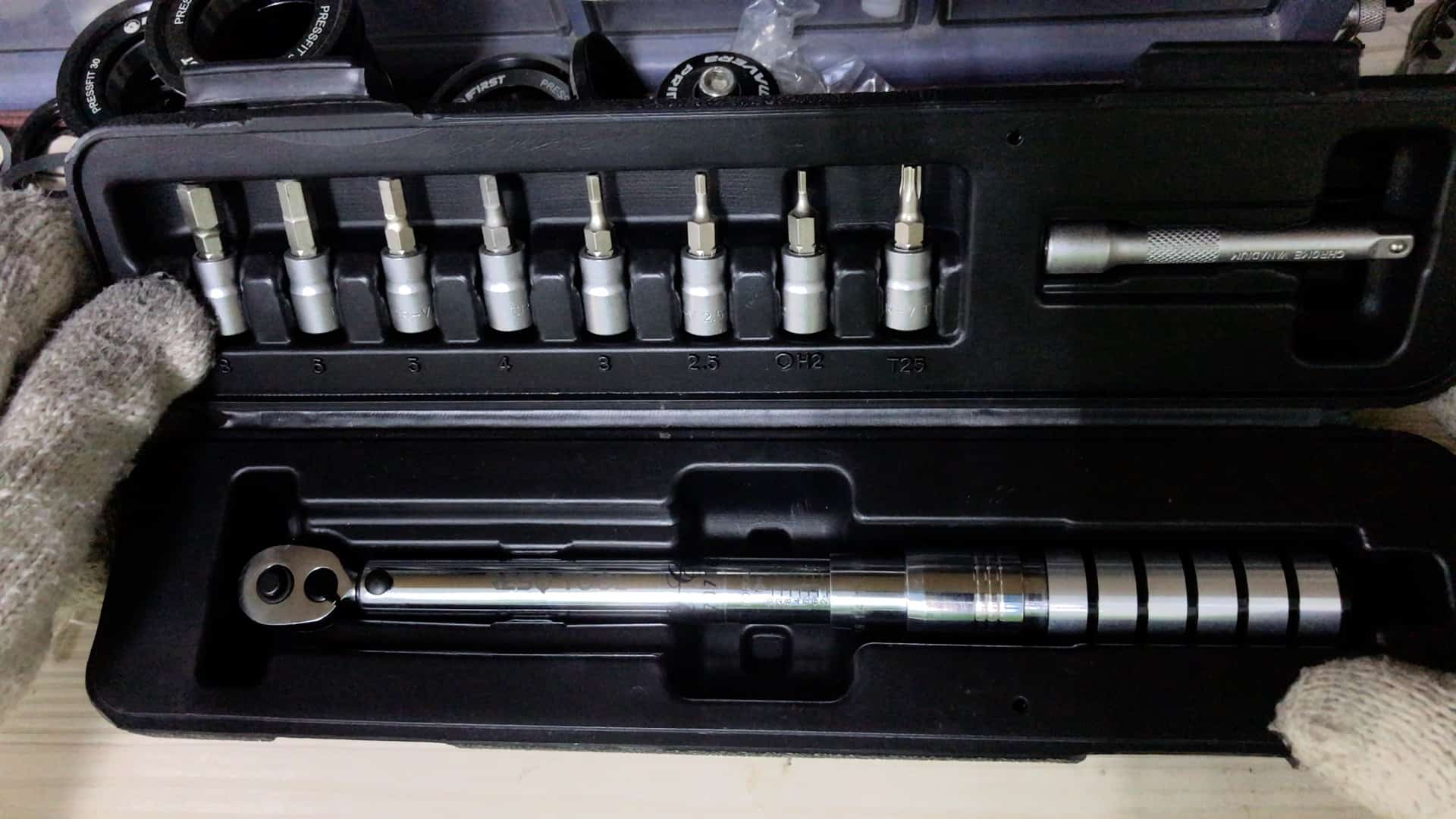
For most bolts you’ll need a torque wrench set that has sockets ranging from at least 3mm to 8mm and a torque setting calibration from 1 Nm (Newton Meter, the unit of measurement) to 25 Nm or so, which will cover almost every situation.
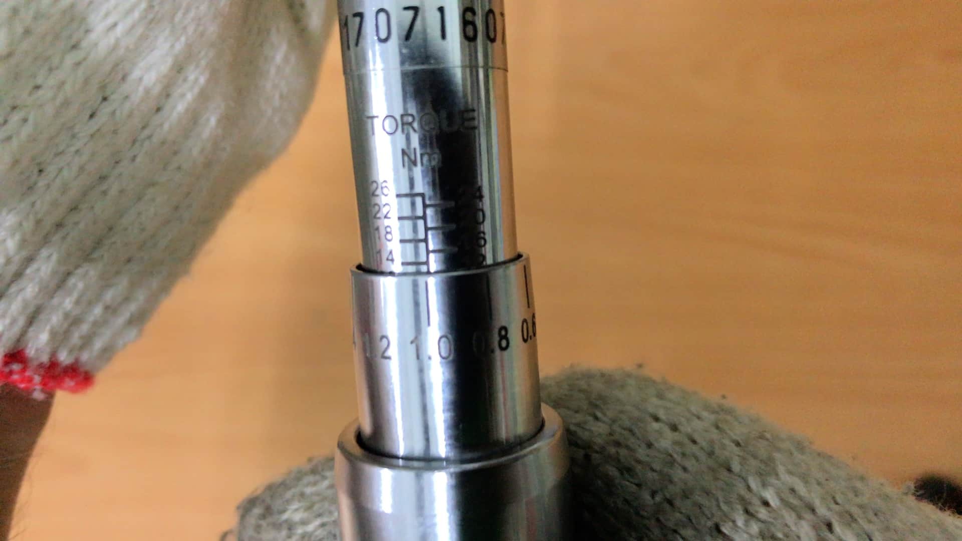
A torque wrench allowing incremental calibration is the best type to get.
NOTE: always undo the tensioning bolt completely when you finish using the wrench. Storing it under tension will distort the spring giving you incorrect settings over time.
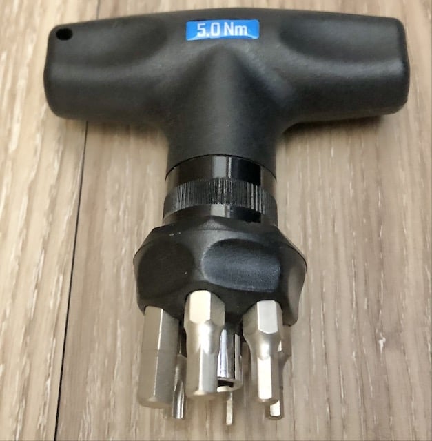
A single-setting torque wrench such as this one fixed at 5 Nm will do if that’s all you’ve got, since 5 Nm is the most common calibration across components and will do in most cases.
This type of torque wrench will fit 2mm – 6mm hex head bolts.
A heavy duty torque wrench ranging from around 28 Nm to 100+ Nm is required for bottom brackets.
A range of suitable torque wrenches are readily available online; you’ll find them with a quick search.
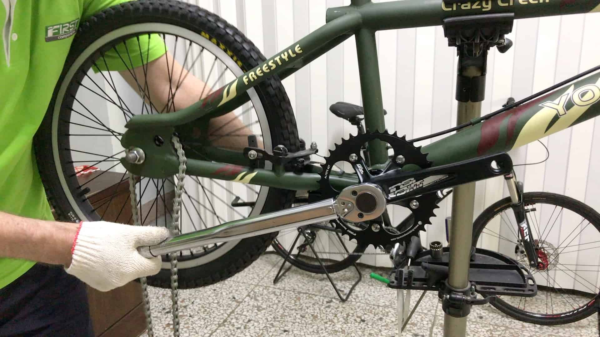
Gloves
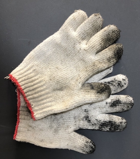
A pair of gloves protects your hands from injury: when a wrench under pressure slips, you’ll often take a piece out a finger or hand. Gloves insulate your hands from these impacts.
They also save you from continual hand washing especially if you are swapping an old, dirty part out for a new clean one.
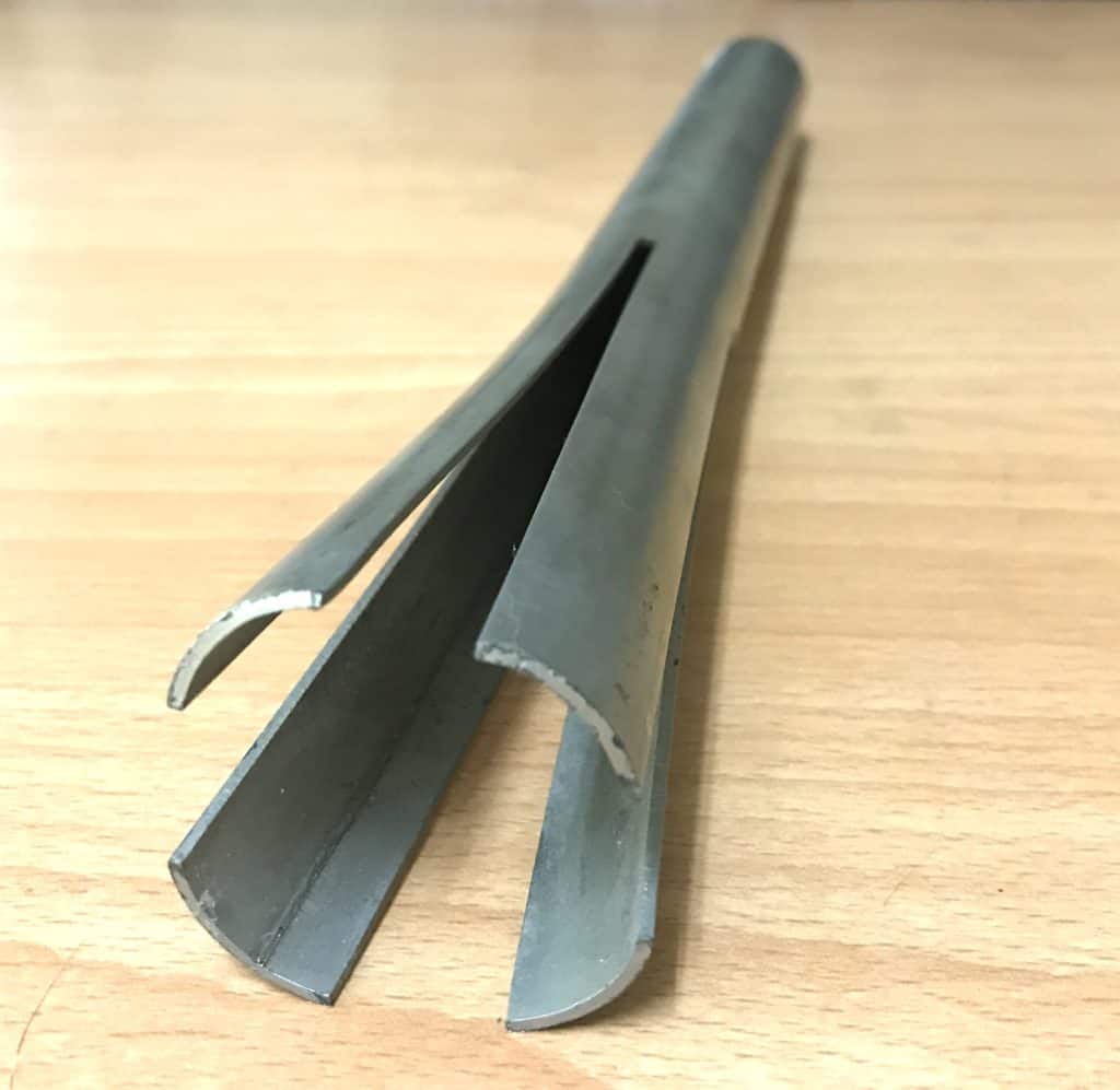
Chain “Cutting” Tool
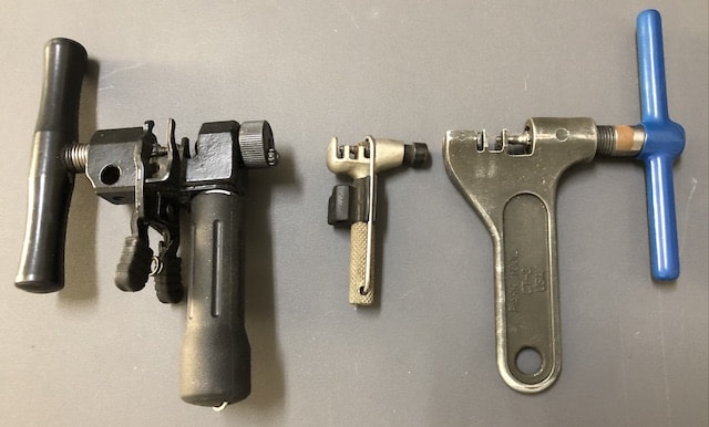
This type of tool does not actually ‘cut’ the chain, although that’s commonly how bike pros refer to the process.
The tool’s pin presses against a chain link rivet, removing it, thus breaking the chain at that link.
Compact, inexpensive chain cutting tools are readily available online.
The tool on the right is by Park Tool, simple and robust.
The chain tool on the left includes a quick release link opening tool; the middle tool is portable and uses a 5mm allen wrench as the lever. It’s also good for occasional use in the home workshop, but not if you are doing many bikes.
Wheels: Tires, Tubes, Cassette
If you are building a new bike, it helps to prepare your rear wheel in advance.
And if you do the rear wheel, it’s easy to go with the flow and prepare the front tire as well, which only involves installing the tire and tube at the same time—you don’t interrupt the flow of the bike build process to fit the tires, install tubes, then the cassette. Just install the rear wheel straight into the dropout.
Install (or replace) a (tight) Tire on Rim
A tubeless or tubular tire install differs from a standard clincher tire install, the most common tire type across all models of bike on the road these days, including the increasingly popular ebikes and (e) gravel bikes.

Here’s the procedure for clinchers:
1. Make sure the rim tape is snapped into position.
Rim tape forms a barrier between an inflated tube and the rim’s spoke holes.
During inflation the tube expands into the spoke holes and ruptures under moderate pressure if tape is not installed.
2. Slip the far side tire bead over the rim
3. Slightly inflate the tube then push it up inside the tire evenly right the way round
4. Slip the near side tire bead over the rim
This is the point where a tight tire will resist your attempts to get the last bit of bead over the rim
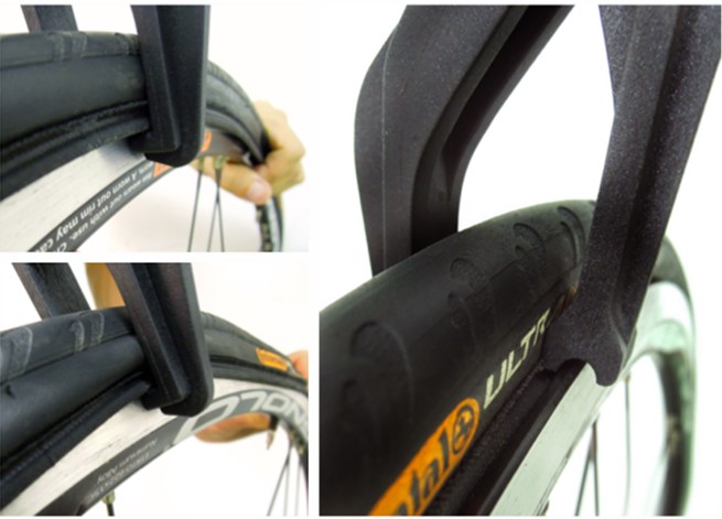
Where a tire is especially difficult to mount, you may need a heavy-duty tire mounting articulated lever such as a tire bead jack.
5. Crucially important: ensure the tube is completely tucked up into the tire ALL the way around.
Any section becoming wedged between the bead and the rim will balloon out and burst as you inflate the tire: you’ll need to install a new tube.
This post on mounting a tire shows you the sequence and demonstrates the technique for installing a tire onto a road bike rim, a method which also works for mountain bikes.
Park Tool’s TL-10 tire mounting tool is useful if you frequently install tires, although not if they are tight and hard to fit to the rim.
Rear wheel cassette
Having installed the tire and tube, slip the cassette onto the wheel hub’s cassette body.
You need the right socket for tightening the lock nut to the cassette body.
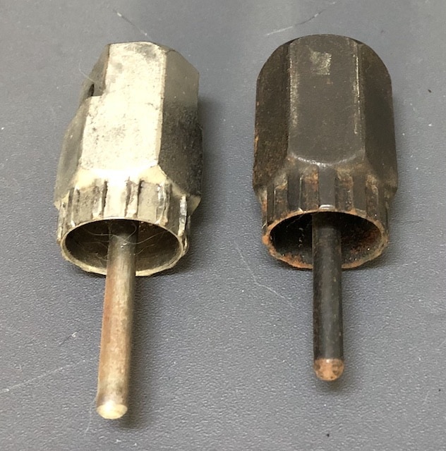
The splined tool on the left fits Shimano and SRAM and most any other standard locking. The tool on the right fits Campagnolo.
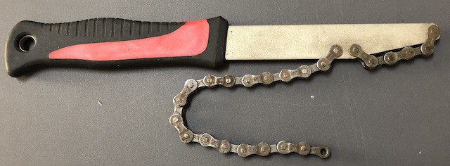
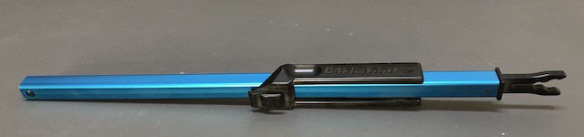
You’ll need this chip whip tool if you’re going to install a cassette.
It stops the cassette from rotating; fixed in position, you tighten the lock ring against it with an open ended wrench or a crescent wrench.
This clip shows how to use a wrench and chain whip together (the mechanic is removing the lock ring in this case, but be aware that installation is the reverse procedure).
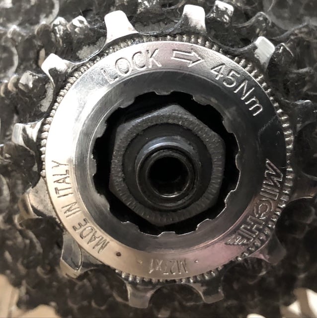
You must use a torque wrench to secure the lock nut at the correct degree of tightness. If you don’t, the nut will be either too tight or not tight enough.
Too tight: swapping the cassette or replacing worn or damaged sprockets is impossible if you can’t remove the lock nut.
Too loose: clunky shifting since the chain won’t efficiently move from one sprocket to another; you will not be able to shift at all.
The recommended lock nut torque for most wheels is 40 Nm.
Frame
A recommended procedure for preparing a threaded bottom bracket shell to receive a corresponding threaded bottom bracket is tapping and facing. (No such requirement for press fit bottom bracket setups).
If you are working with a cheaper, low end bike, you can overlook this process.
However, the procedure should be perfomed on mid-end bikes, and certainly high-end bikes.
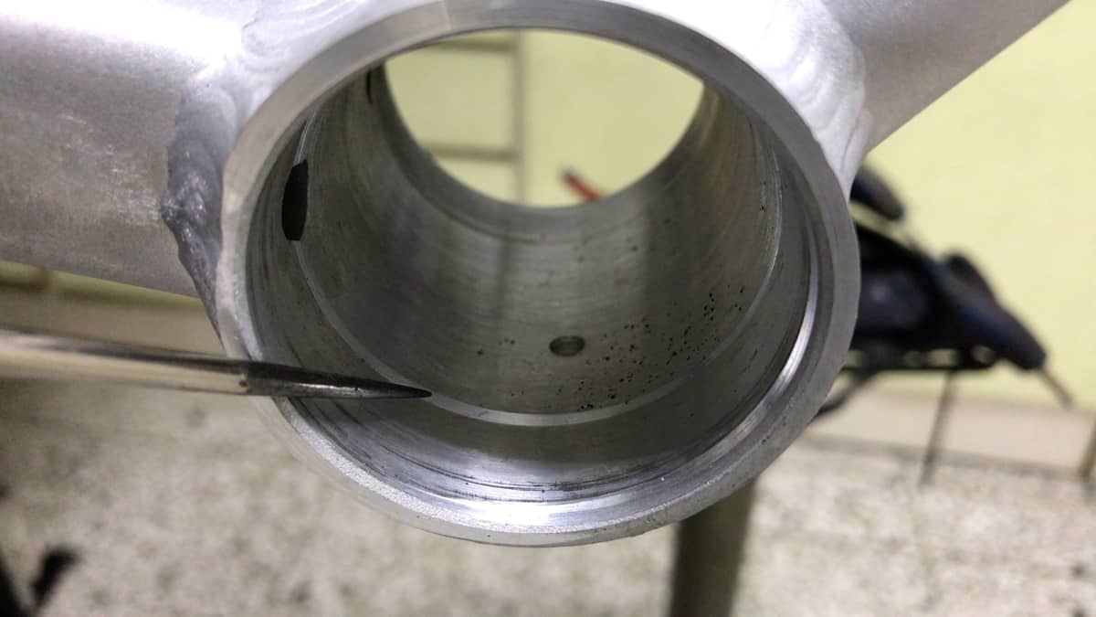
Tapping
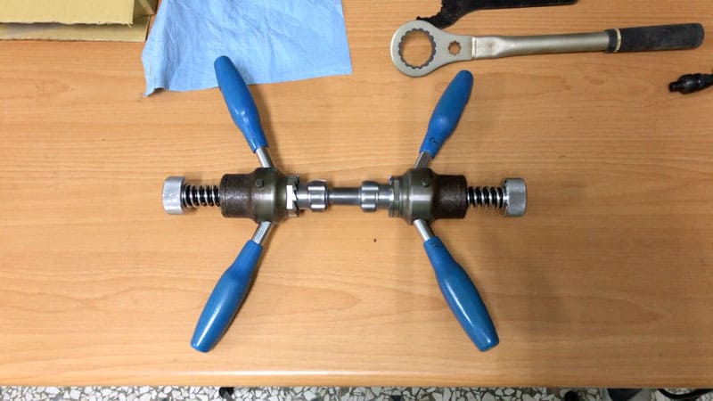
Running a die through the threads smooths out any manufacturing burrs or imperfections.
Tapping increases the likelihood that a bottom bracket can be installed with little resistance, even without a tool (although a torque wrench is required to finish off the install).
Resistance can be mistaken for cross-threading. Or, worse, cross-threading can be mistaken for resistance in which case you will ruin both the bottom bracket and the bottom bracket shell threads.
Slowly turning the tapping and facing tool’s handles rotates each die into, and along, the BB shell threads, cutting the threads perfectly smooth.
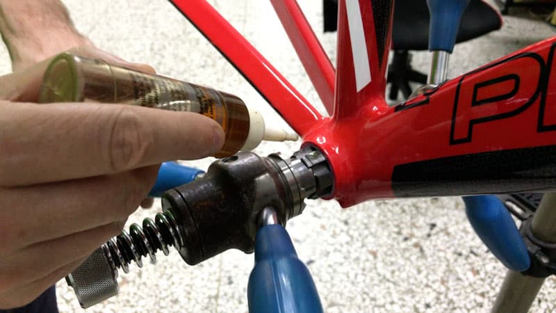
Facing
The objective is to remove paint overspray together with the top 0.1-0.3 mm surface from a bottom bracket’s outward facing edge (the “face”) for external bottom brackets.
An external bottom bracket cup’s inside face tightens onto the BB shell face. It comes out of the factory precisely machined and so should, ideally, mesh with a corresponding precisely machined surface.
Facing the BB shell creates that surface. The facing tool’s carbon steel cutting edges produces a result comparable to what you would expect from CNC machining.
An example of the complete tapping and facing process is detailed in this video clip: https://youtu.be/tbWSkRsHr3o?t=117
Derailleur Hanger
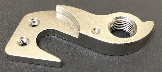
If the frame does not come with the hanger pre-installed, then now is the time to bolt it on.
Note that derailleur hangers are frame-specific. Each manufacturer designs a hanger for a frame model or perhaps across several models.
So, be aware that you will not, in all likelihood, be able to obtain a hanger for your frame in the aftermarket, but rather direct from the manufacturer or their agent.
Hangers commonly have either one bolt or screw, or two.
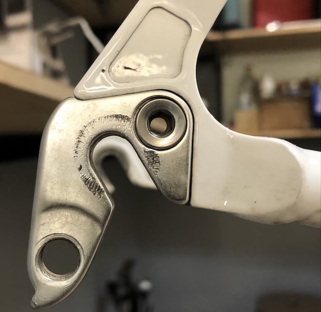
A single bolt derailleur hanger bolts into a nut on the opposite side with a 5mm Allen wrench;.
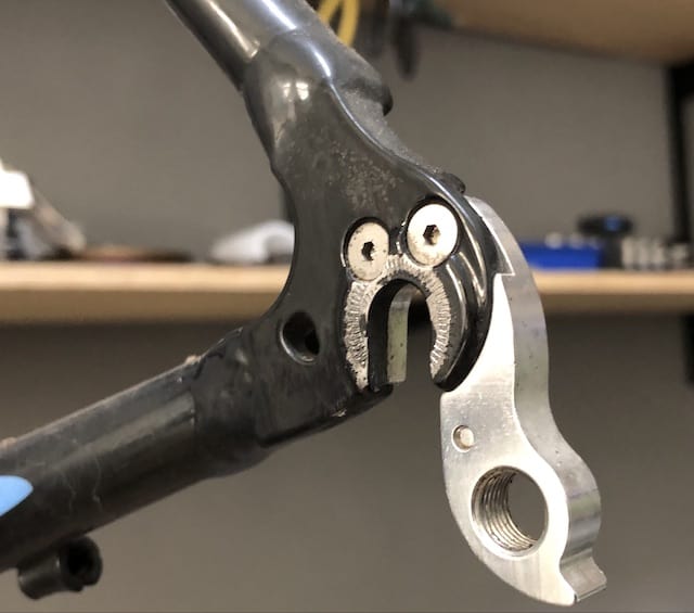
The two bolts of this type thread directly into the hanger with a 2mm Allen wrench.
DRIVETRAIN
The approach to building a bike in this article separates the build into two parts:
- The drivetrain
- The ‘front end’.
Working with the bike, adjusting the crank and tightening the bolt(s) is easier without the forks impeding access from the front.
Another thing is that having completely assembled the rear, including fixing the rear wheel in the dropout means it’s ready to
1. GET A STAND FOR THE FRAME
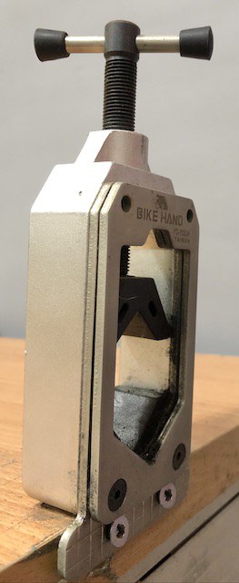
You need a reliable stand on which to mount the frame as you are building a bike.

This folding model by Bike Hand is designated a “repair” stand, but is perfect for building a bike.
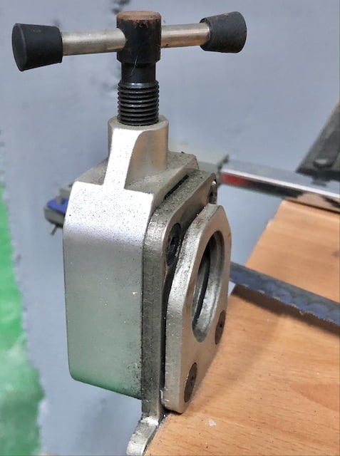
Another solution is an L-shaped bracket with a clamp which bolts to a wall or bench.
NEVER clamp a carbon frame in a stand on either the top tube or seat tube—you can fracture the carbon.
You can get away clamping an alloy or steel frame by the top tube, although that makes routing brake and derailleur cable housing difficult.
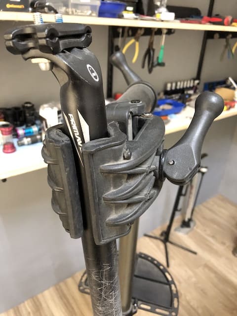
The best method is to clamp the seat post into the seat tube, without the seat of course. Then tighten the clamp’s jaws onto the seat post, insulating them with cloth or polystyrene or something similar if you are using the actual seat post that will be used on the bike.
Bicycling’s guide to repair stands is a good introduction to the range of models available.
With the frame firmly positioned in the stand, lay out the components ready to go.
2. BOTTOM BRACKET
Although every stage of building a bike is important, the bottom bracket stage is especially important: you will ruin your frame and your bottom bracket if you don’t get it right.
Threaded BB
There are two types of bottom bracket in this category: cartridge or external.
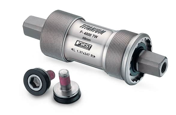
A cartridge BB installs inside the bottom bracket.
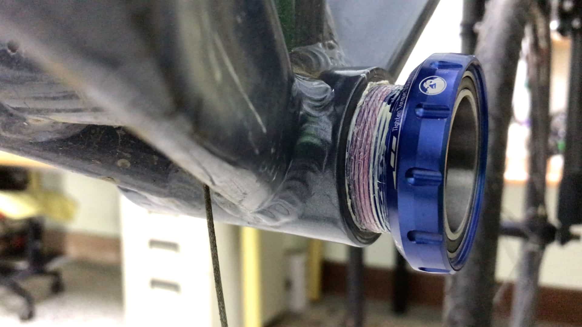
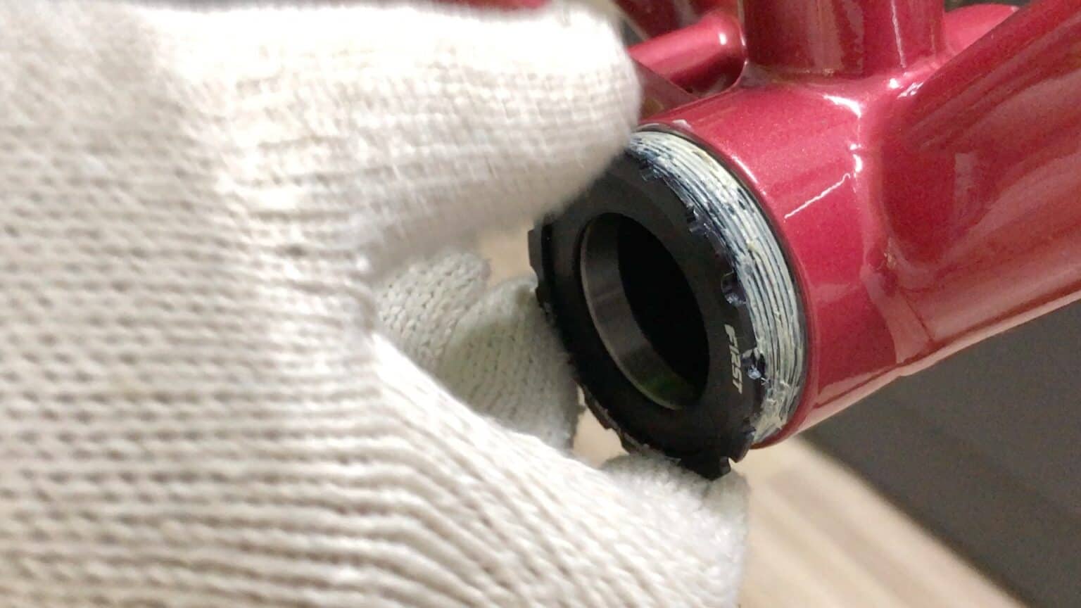
An external BB has bearing cups which screw into the shell, but the bearings sit on the outside.
Installation technique
You’ll have a smooth BB installation experience if you’ve following the tapping and facing preparatory steps outlined above.
A generous coat of grease for both the BB threads and the BB shell is mandatory.
The problem to avoid is cross threading the BB cup into the shell which will strip the thread from both the —and it’s easily done.
The trick is to seat the cup threads into the BB shell threads correctly.
Then you can be sure that if there’s resistance early in the install, it’s not due to cross threading.
Place the cup on the shell threads, then gently turn the cup in the direction opposite to the install. (To the right on an English threaded drive side as this is a left-hand thread).
With a half to one, or one-and-a-half, centimeter turn you’ll feel and perhaps even hear a “click” as the threats mesh together.
If that doesn’t happen, turning the BB slightly backwards and forwards will allow that meshing to occur.
This video clip demonstrates the technique.
The BB is seated, quickly turned right; it seats, then the install continues in the correct direction.
Tools
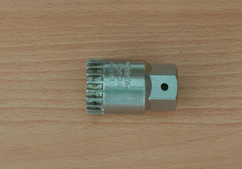
A splined socket is used to install cartridge threaded BBs
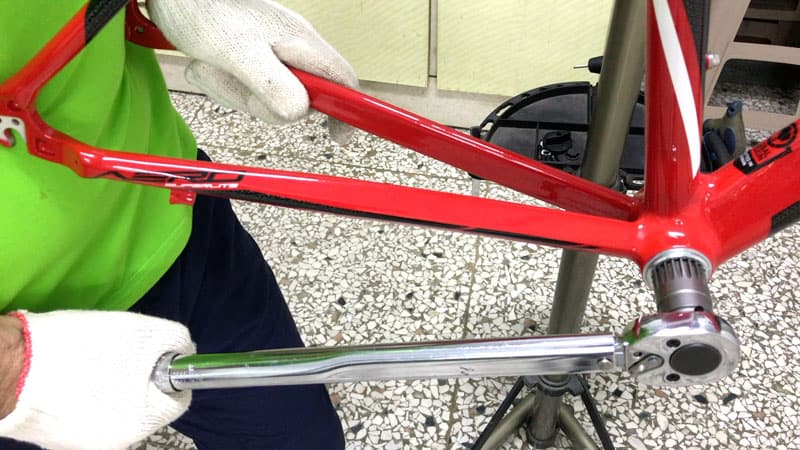
Then you should use a torque wrench to tighten the bottom bracket to the correct tolerance.
The range is normally in the order of 35 Nm to 50 Nm.
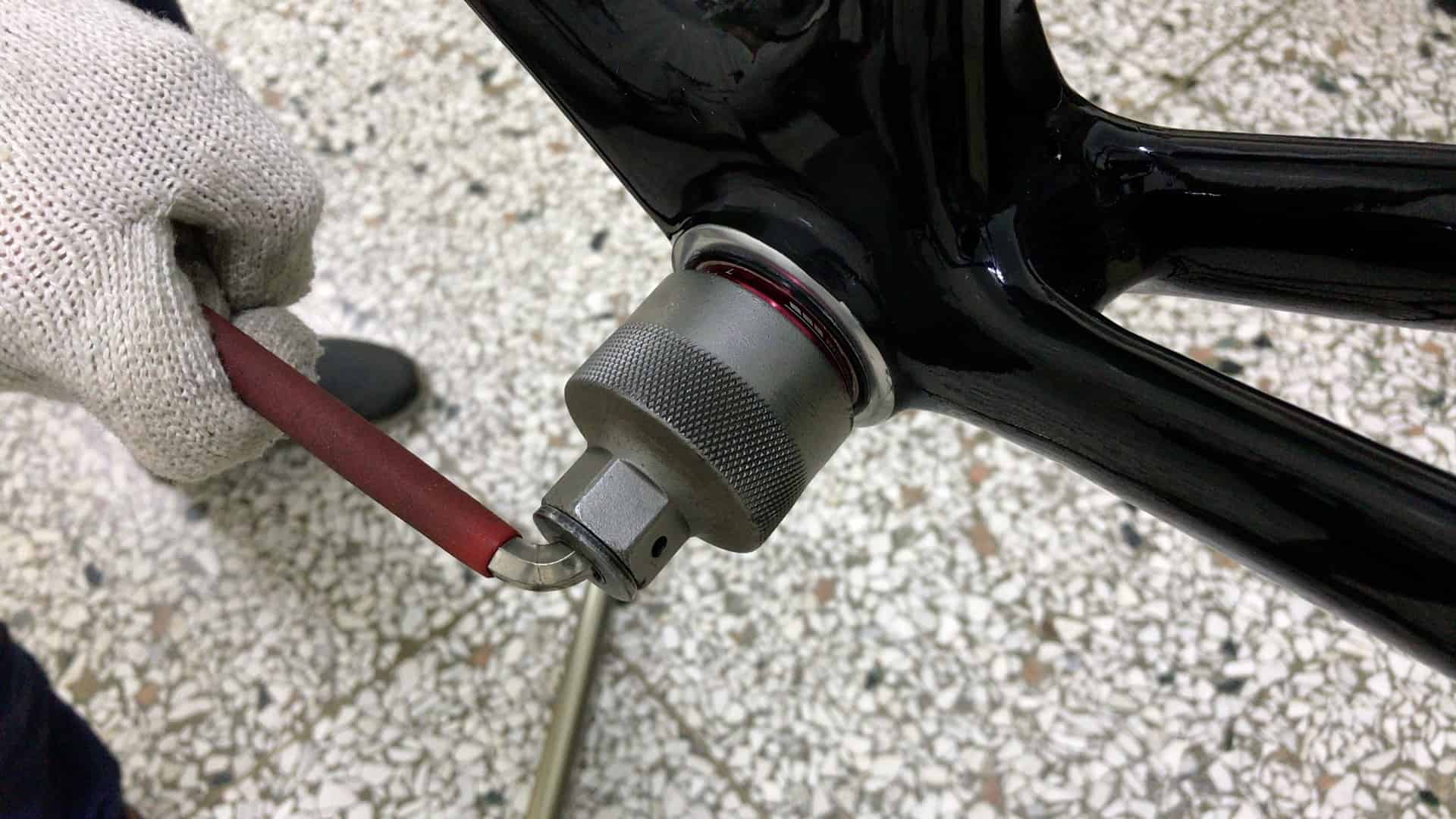
An external BB is tightened with a socket that fits over the bearing cup.
If you don’t use a torque wrench, the bottom bracket might be too loose which damages both the BB threads and the shell threads due to the forces exerted on the crank when a bike is ridden.
Over-tightened cartridges or BB cups may be impossible to remove when you need to.
Press Fit BB
BB30 is the original press fit bottom bracket. It is also the most tricky to install.
You need specialist tools and a good deal of experience to get it right.
My remarks here refer to the more popular PF30 and BB86/90 standard which is more straight forward and the most likely BB setup you’ll be dealing with if, indeed, press fit is your thing.
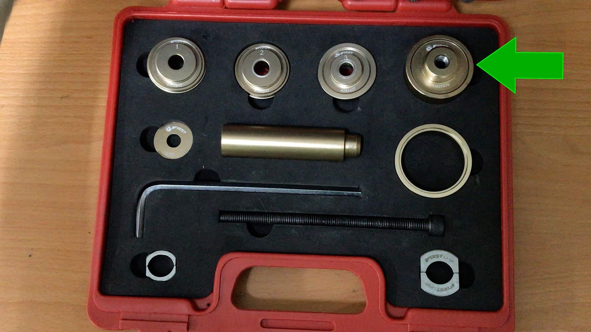
You still need a specialist toolset that enables you to gently slide a press fit bearing cup fully into a bottom bracket though.
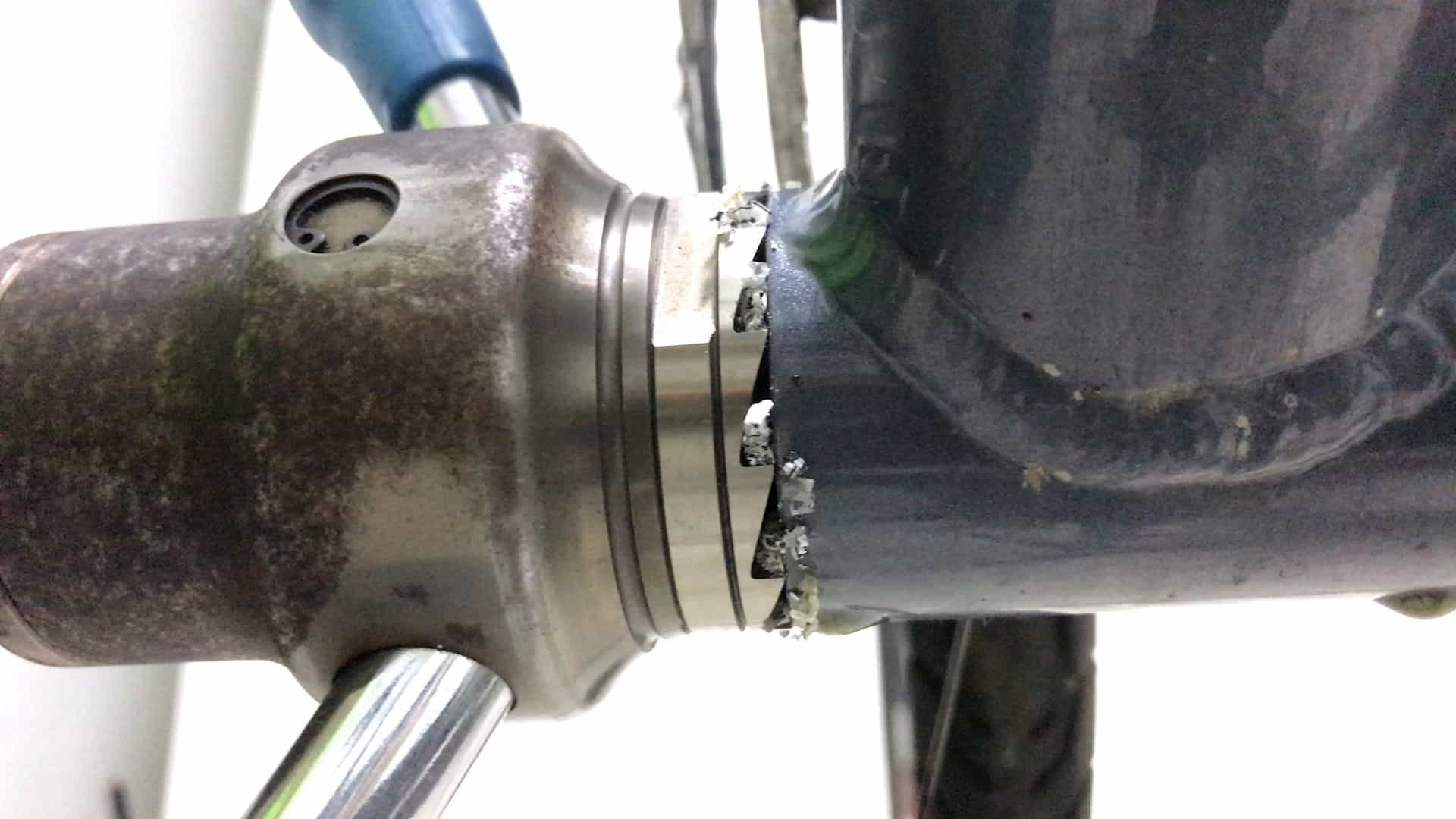
And even more important, you need the right tool for removal: you should avoid impact tools such as this one.
The blades can crack the inside face of a bearing cup. Plus the cup often is often suddenly ejected from the shell onto the floor.
Either way, damage to the bearing cup means you can’t re-use it.
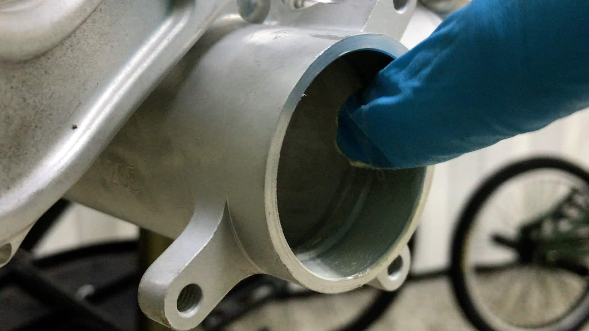
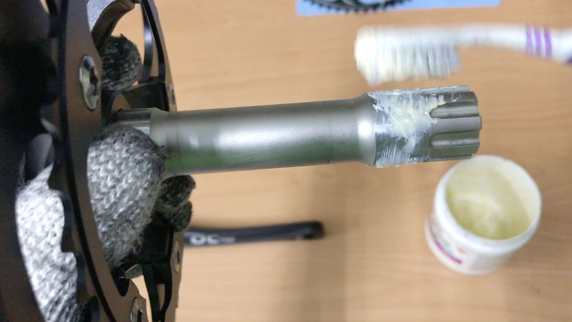
Grease the BB shell.
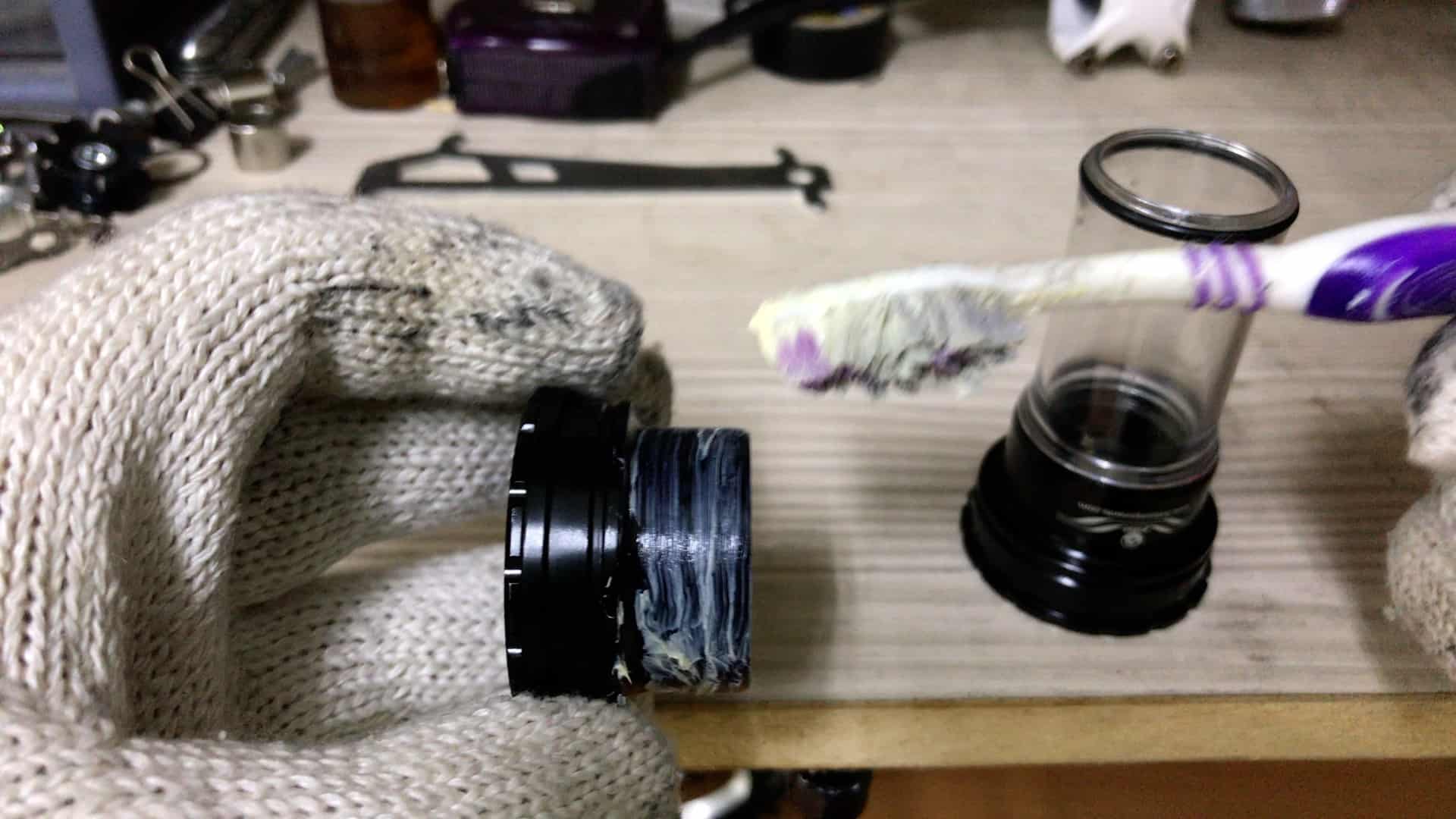
And the bearing cups (use of a toothbrush is optional…)
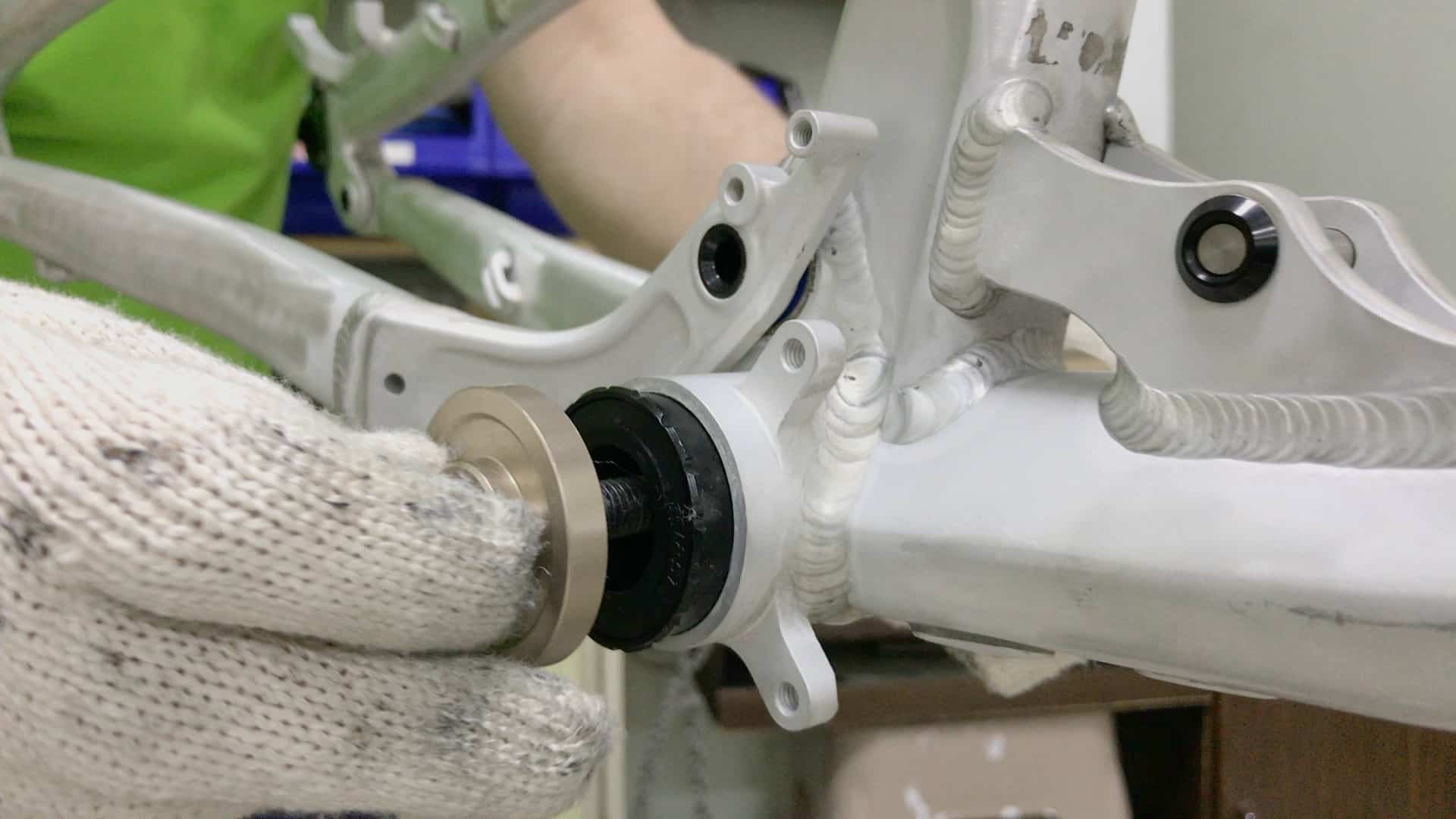
Insert the disc and its bolt into the BB cup.
A cup threads onto the bolt on the opposite side, providing a brace against which the bolt tightens.
Turning the bolt exerts pressure against the cup, pressing it into position. Reverse to to the other side.
This video covers the process in detail.
3. CRANKSET
Installing a crankset is one of the easier stages in building a bike.
Once the bottom bracket is installed you
- slide the single piece crank through, or
- insert the integrated spindle then bolt on the drive side crank, or
- bolt the drive and non-drive cranks to the spindle
Single Piece
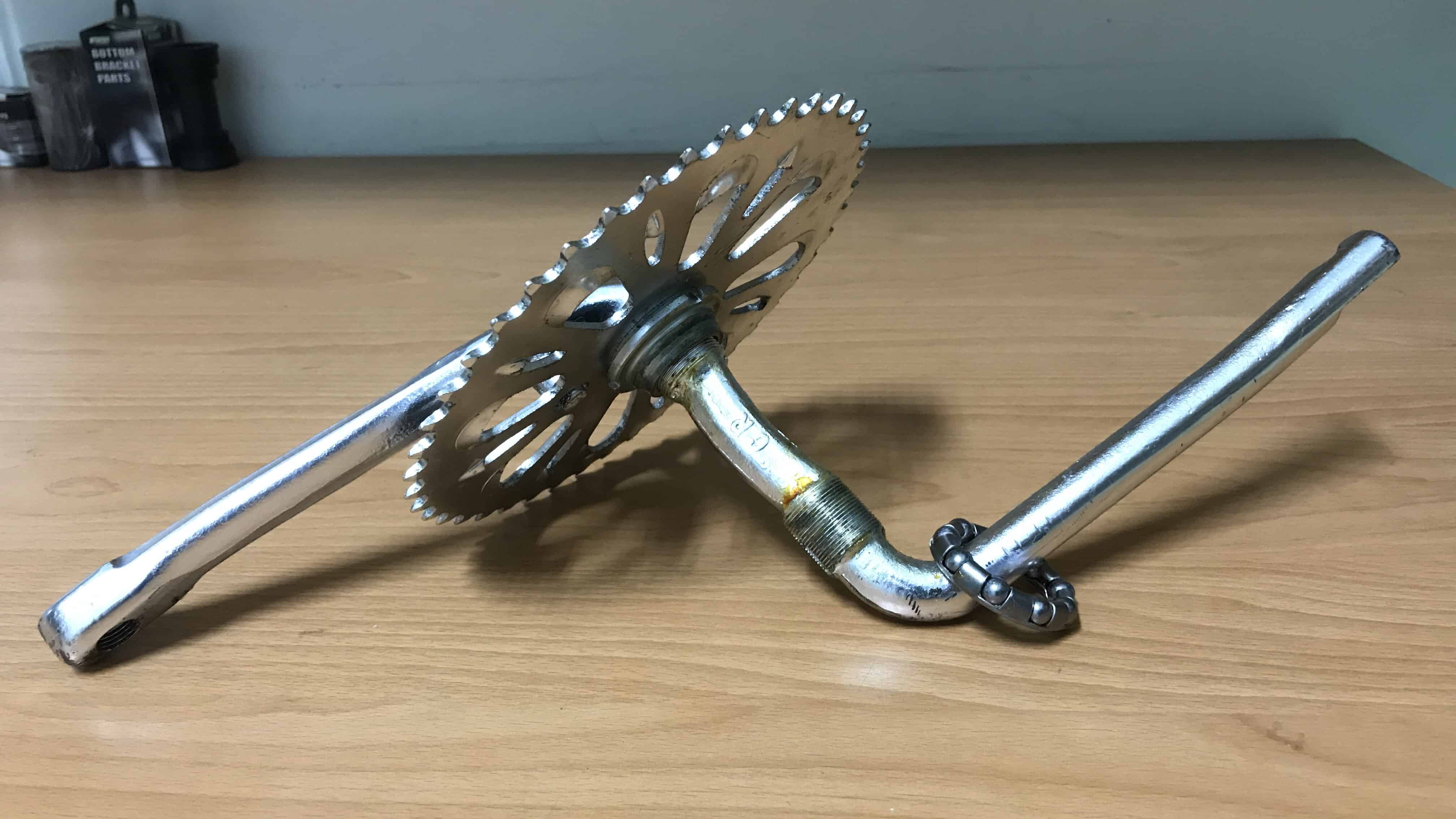
Unlikely you’ll be installing a single piece crank into an existing bike, but rather either repairing, maintaining or upgrading to a lighter, higher quality crank.
Here’s our video on the upgrade procedure from one piece to a three piece crank.
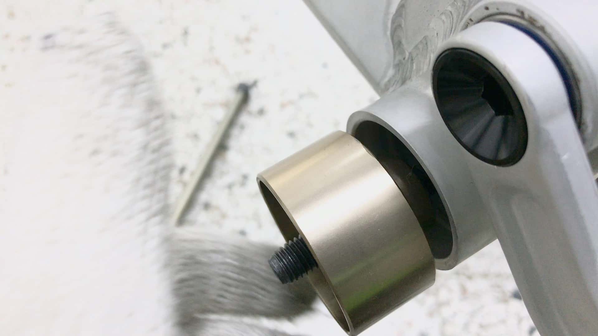
INTEGRIERT
If you are building a bike in the mid- to high end range, you’ll be looking to install an integrated crankset.
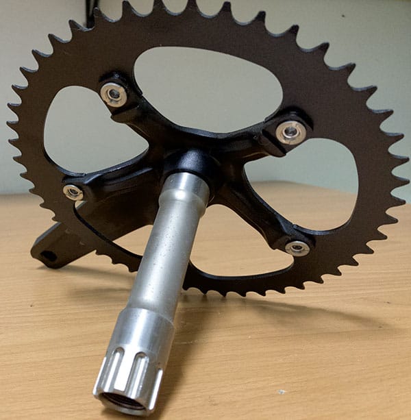
Why “integrated”? Because the spindle is fused to the drive side crank making a two piece crank you could say.
The spindle normally fits tightly to the bottom bracket’s internal diameter (it should in order to avoid even the tiniest degree of movement stemming from an imperfect fit) which means it will resist being pushed into position and even stick against the bottom bracket.
Applying a smear of grease over the spindle’s surface makes positioning the crank in the bottom bracket much easier.
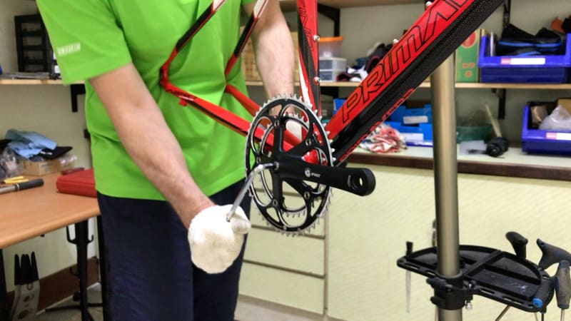
Some cranks will still resist, requiring you to tap them with the heel of your hand—wearing gloves is essential for this.
Two or three solid thumps is usually all it takes.
But where a crank is really tight, place a thick cloth or toweling over the spider and give it a few taps with a rubber mallet.
Driving the crank home over the last centimeter often requires a few taps of a mallet.

An 8mm socket is a good addition to your tool kit for securing M8 cranks to the non-drive side (SRAM for example). Otherwise, a 6mm fitting is what you’ll need.
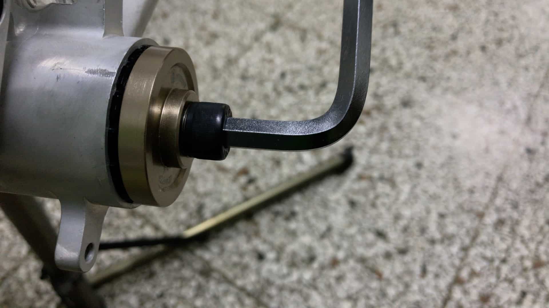
Three Piece
If you are building a bike on a budget, a cartridge bottom bracket in an alternative to the higher end integrated crank.
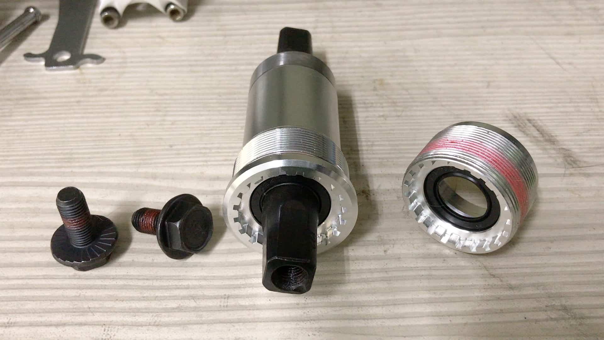
The spindle is housed together with the bearings in the cartridge body.
Two cranks individually bolt onto the left and right sides of the BB spindle.
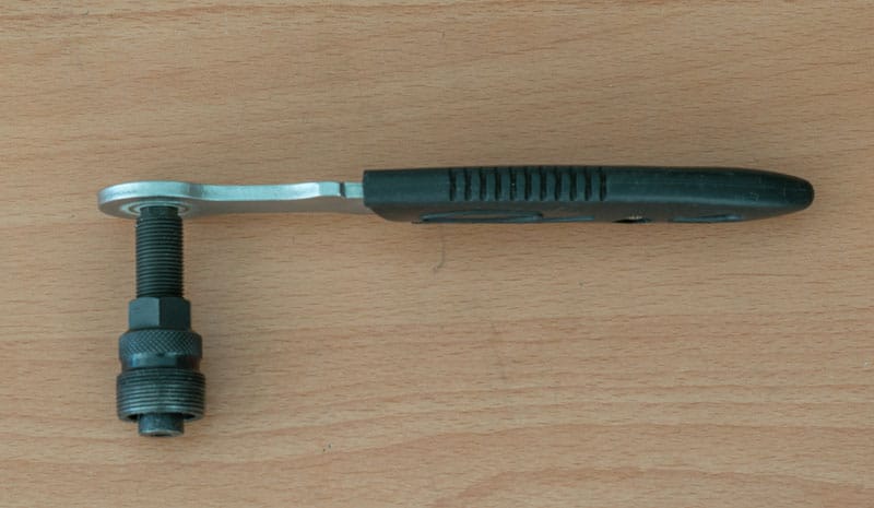
You’ll need a crank removing tool to remove the cranks from each side, however.
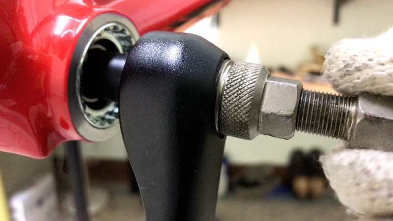
The tool threads into the crank. Then you turn the bolt which pushes against the spindle, slowly removing the crank from the spindle.
This video demonstrates the key issues in detail.
4. FRONT and REAR DERAILLEURS, and REAR WHEEL
If you are building a bike that has a double or triple chainring, once you’ve installed the crank installing the front derailleur fits into the work flow.
And if you’ve done the front, you may as well do the rear as well, a one-two punch.
Front Derailleur
Where you have a separate clamp, loosely bolt the derailleur to the clamp before installing the clamp onto the seat tube since it’s a little more difficult to fit the bolt and hold the derailleur square against the bracket at the same time.
Loosely clamp the derailleur to the seat tube.
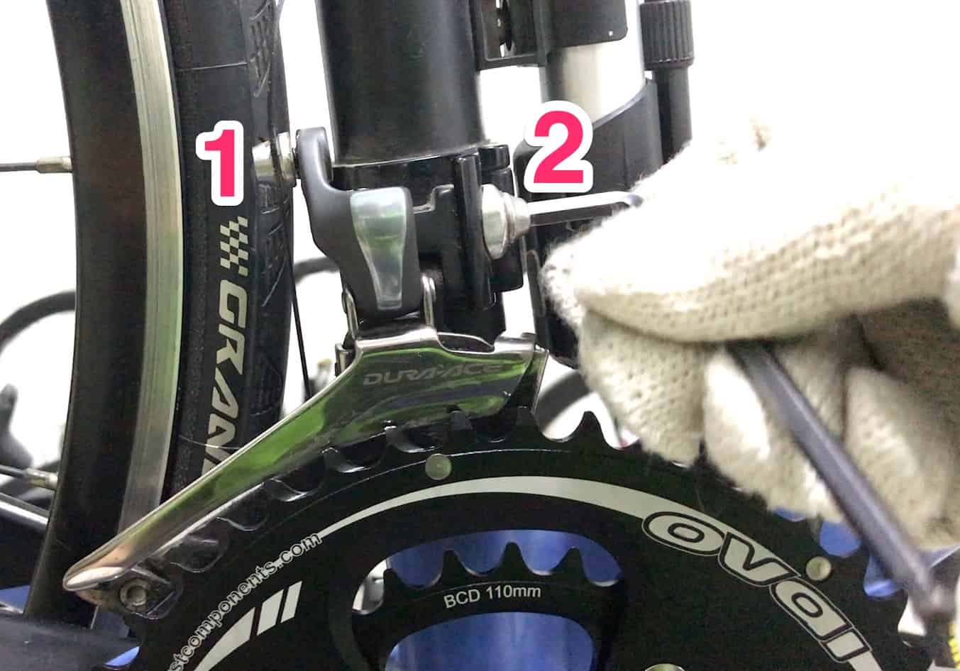
Adjust the gap between the derailleur cage and the apex of the chainring teeth: minimum of 1mm; maximum of 3mm is the rule of thumb.
You do that by loosening the bolt then sliding the derailleur up or down (2). (“1” is the cable clamp bolt).
Having got it right, tighten the bolts enough to hold the derailleur in position (we tighten all bolts to torque tolerance at the end of building a bike each time).
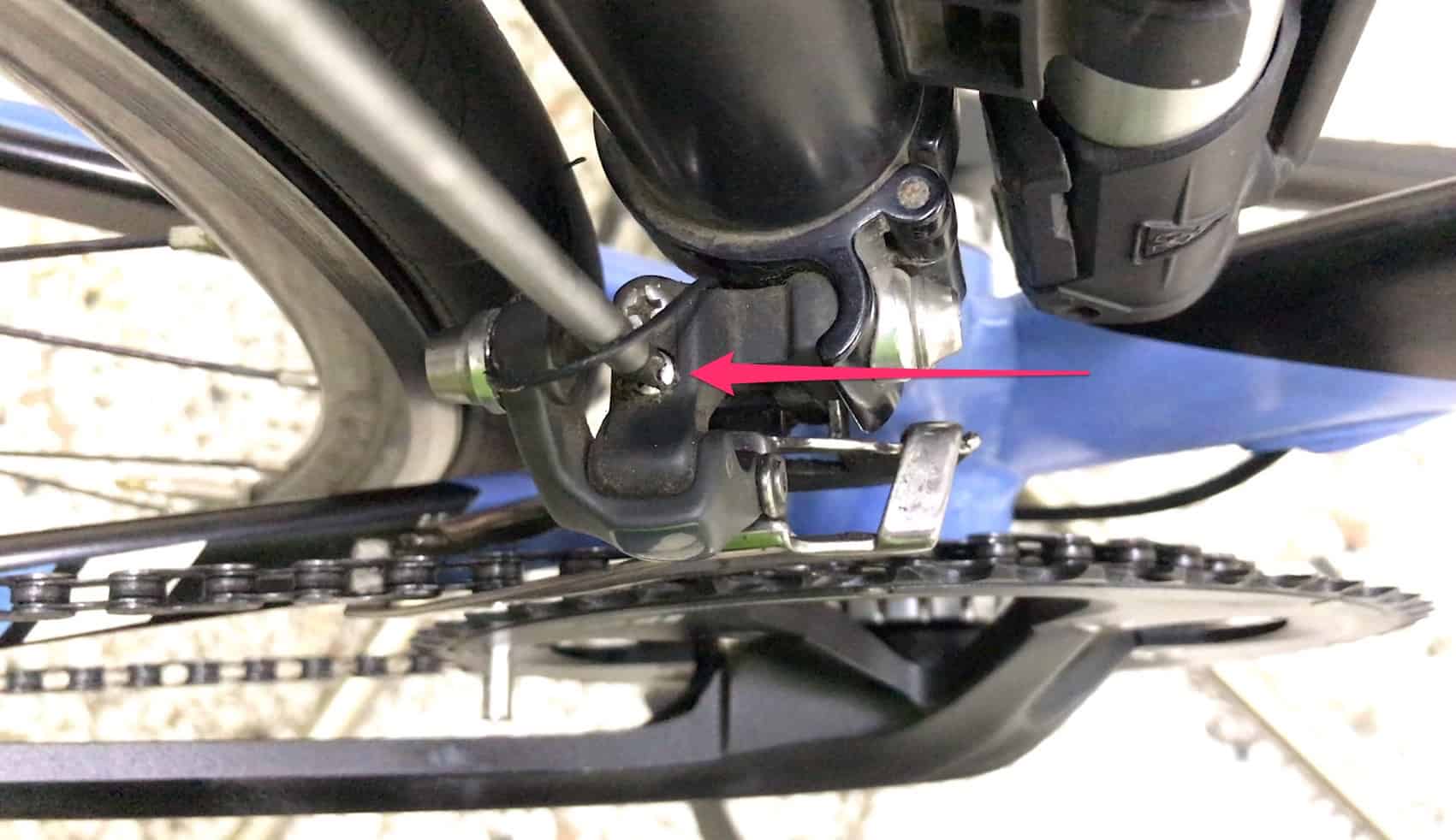
The derailleur limit screws control the cage’s position relative to the chainring, which in turn allows fine adjustment of the shifting once the shifters and cables have been fitted.
On most front derailleur, the screw on the inside controls cage position relative to the inside chain ring; the outer screw adjusts the cage relative to the large chain ring.
Right now you need to move the cage so the outer edge is in direct line with the chain ring as you look down from above.
This is what tuning the front derailleur through the limit screw looks like.
NOTE: follow the specific instructions for the latest generation of high end derailleurs from Shimano and SRAM (eg. the ‘Yaw’ system).
Rear Derailleur
The rear derailleur bolts onto the derailleur hanger. Smearing a little grease smooths the install and is a great help when removing the derailleur.
It’s easy to cross thread the derailleur bolt, so take extra care to seat the bolt correctly in the hanger’s threads, then proceed slowly.
NOTE: These bolts screw in very easily, so any resistance at all means you are cross threading and will probably ruin the hanger threads at the least. Reverse the direction, remove the bolt, then try again.
If you are fitting a new derailleur out of the box, due to the factory default settings you need to move the cage outwards a distance of up to a centimeter so it is level with the smallest sprocket.
The rear derailleur limit screws are normally marked “H” for the outer limit, and “L” for the inner limit or something similar. “
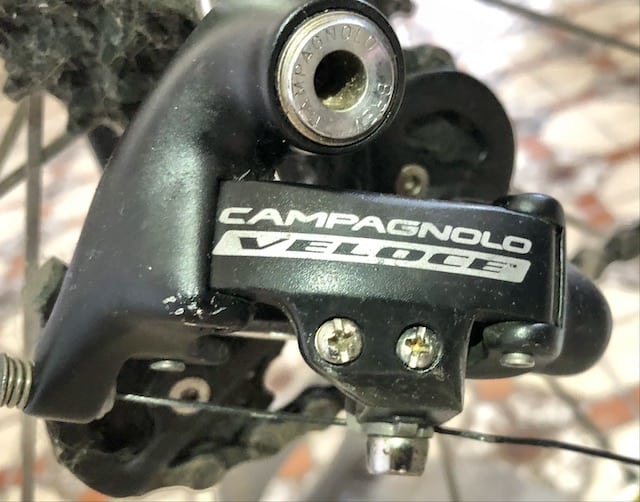
On some derailleurs such as this Campagnolo lower end model, the outer limit screw is located in front of the lower limit screw.
If you are not sure which is which, pull the derailleur towards you as far as it will go then try each screw in turn: the outer limit screw is the one that incrementally moves the derailleur.
The video illustrates the procedure (a recumbent, but the principles are the same)
Install the Rear Wheel
Having assembled the front and rear derailleurs to the frame, install the rear wheel into the rear dropout.
Now you can install the chain.
5. CHAIN
There are two tricky maneuvers to get right when installing the chain:
- threading the chain through the rear derailleur’s cage
- joining the chain
Threading the Chain Through the Derailleur
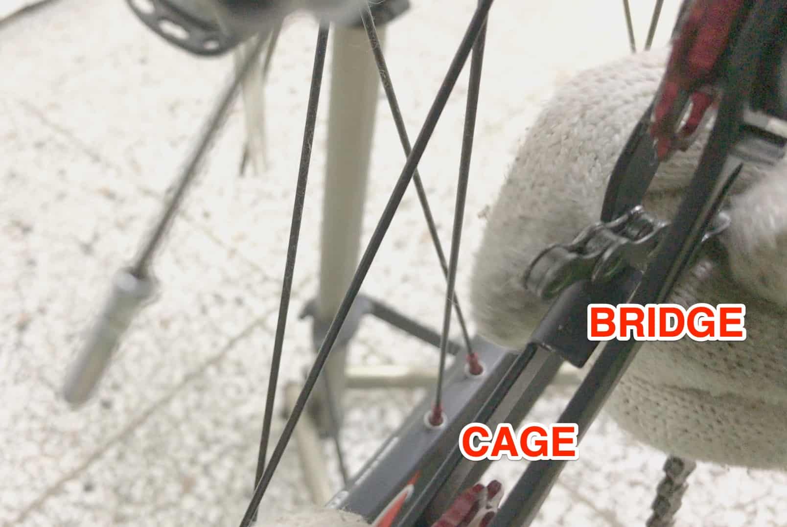
Thread the chain into the cage making certain it is on TOP of the bridge then run it over the top of the lower pulley wheel.
Pull the chain almost all the way through
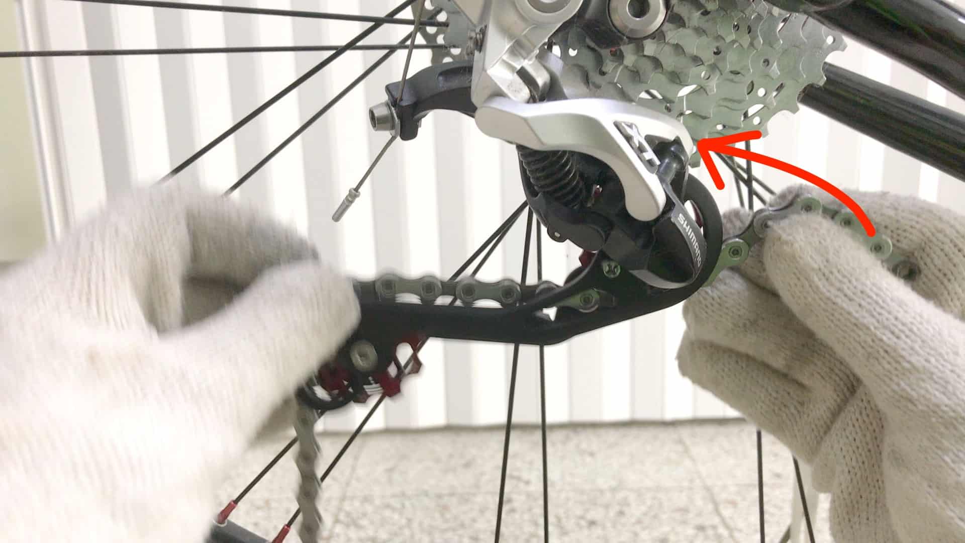
Then thread the chain over the top of the upper pulley wheel
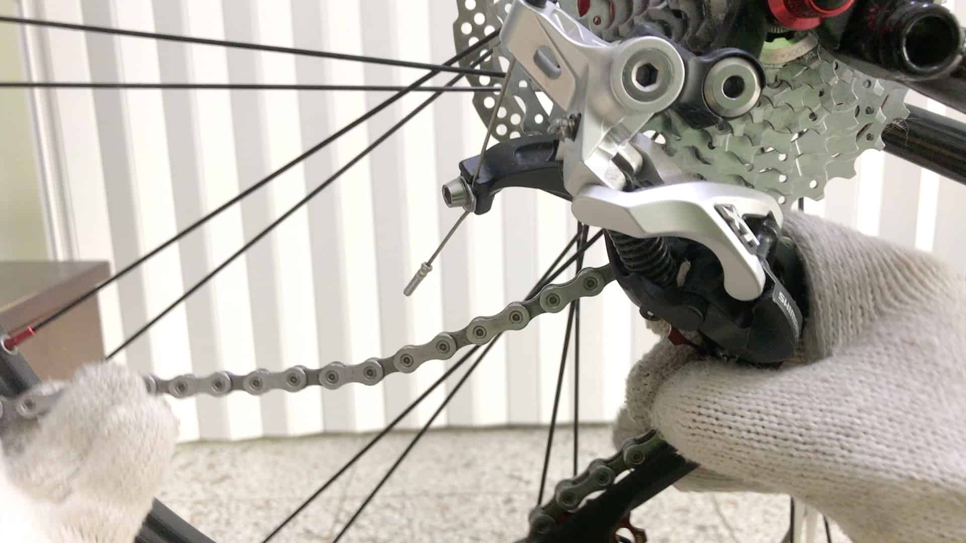
Then pull several centimeters of chain through, enough to lay it up and around one of the cassette sprockets situated above.
Now pull the chain through to the front derailleur, thread it through and onto a chainring, then around (rotating the crank).
You will end up with a loose end hanging from the rear derailleur lower pulley. Leave the other end dangling from the chain ring.
Joining the Chain
The two things to get right when joining the chain: the length and the connection itself.
With regard to safety, the quality of the connection is most important.
Chain Length
You minimally need around 1cm clearance between the chain and the rear derailleur cage.
The chain must come into the lower pulley move through the drive train without touching the cage on he way in.
If in doubt as to the exact length, cut the chain bit by bit
This video details the process on a recumbent trike (the principles are the same). You’ll see the chain measured and the the rivet removed. The chain is then connected using a quick release link.
Connecting the Chain
Never, ever, rejoin a chain using the rivet that you press out of the chain. It is possible to push the pin 95% of the way out when cutting the chain, and then reuse it to rejoin the chain.
Bad idea. The chain is highly likely to give at that point, sending a cyclist into the ground.
Use the special purpose pin that manufacturers (usually) include with a new chain or a quick release link.
This video clearly shows the method of threading the chain into the cage, onto the sprockets, then joining with a QR link.
The QR link is the best method allowing you to join a chain rapidly and securely.
QR release technique: getting it right and what to avoid in the process.
Install the Rear Brake
Bolt the rear brake onto the brake bridge—along with the front brake, probably the easiest component to install.
FRONT END
With the drive train installed and functioning, the first half of building a bike is complete.
The next half involves installing the fork, followed by the stem and handlebars, then the shifters, which allows you set up and adjust the gear shifting.
After that it’s simply a matter of wrapping the tape, installing the seat post and saddle, then going over all bolts with a torque wrench to tighten them to the right tolerance.
6. FORK, STEM, HEADSET, and FRONT BRAKE
When you’re building a bike, everything literally revolves around installing the fork correctly.
A fork is comprised of the fork blades, the fork crown, and the steerer.
All forks have the same length steerer upon manufacture.
Fitting a fork to a bike involves cutting the steerer to the correct length. As to the correct length ie. how much is cut off, depends on how high you want the handlebars above the headset, or in other words, the bike’s stack height.
It’s a comfort thing, which varies with every person.
Headset Preliminaries
Determining fork length requires assembling the headset into the head tube and fork.
The steps are as follows:
- Install crown race on the fork
- Slide the sealed bearing down onto the crown race
- Slide the fork up into the head tube from beneath
- Slide the upper sealed bearing down the steerer into the head tube
- Slide the compression washer, spacer, and dust cap into position (continue to support the fork as it can drop to the floor)
- Slide the stem down the steerer onto the dust cap
Note that a smear of grease on each part is good idea once you’ve cut the fork completes the installation.
This video details each phase of the process for a mountain bike.
Measuring the Fork
This stage involves an experimental install of the fork, headset, spacers, and stem.
However much of the steerer projects above the top of the stem is approximately (I’ll explain shortly) how much you’ll cut off.
Install the fork (see previous section) then mark a line around the steerer where it enters the stem.
For an alloy or steel steerer: make another mark 3mm below the line you’ve drawn (in the direction of the fork blades). This is your cut line.
The gap allows a space at the top for the top cap to tighten against the top of the steerer. It it doesn’t, the whole assemblage will be loose.
For a carbon steerer: make another mark 5mm below the line you’ve drawn. That’s your cut line.
The extra 2mm (3+2=5) makes allowance for the extra thickness of the expander you insert into the steerer (star [fangled] nut for alloy and steel steerers).
Cutting the Fork
For alloy and steel steerers a pipe cutter works.
Otherwise invest in the correct fork steerer clamps and use a hacksaw.
You slide the fork in from the left centering the point you marked on the fork as the place to cut within the guide.
Turn the handle to clamp the steerer firmly.
Use a hacksaw with a coarse edge cutting gently at first to create a groove the blade can settle into for the rest of the cut.
Carbon tubes are not built to withstand lateral force and will fracture under excessive pressure. A carbon steerer clamp’s jaws holds a carbon steerer firmly without crushing the fibers, even if you crank the handle too far.
Use a hacksaw with a finer edge in order to minimize splintering the carbon fibers which will make for a messy finish.
As you near the bottom of the cut, loosen the clamp and rotate the steerer through 180 degrees.
Cut the last millimeter or two back in the direction of the main cut. This will prevent fibers peeling away from the top, again, giving you an untidy finish.
This video clip demonstrates how to use a clamp and cut with a hacksaw.
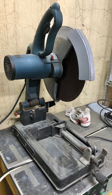
A powered cutter is an option if you are assembling more than one or two bikes a day.
Star Nut or Expander Installation
An alloy, steel, or chromoly steerer requires you set a star nut a few centimeters down to receive the headset tensioner bolt which allows the headset and forks to be tightened into one unit.
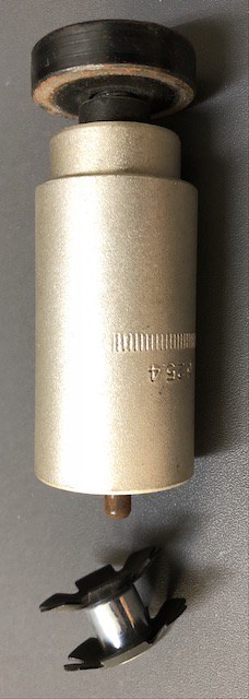
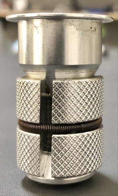
The tool enables you to position the star nut at the right depth as well as square to the steerer.
Place the star nut on the star nut setter’s pin with the blades facing the direction as in the image.
Place the mounted star nut at the top of the steerer and tap with a hammer.
The star nut straightens as you hammer it in—keep tapping until you can’t go any further (the tool determines the depth).
Using a star nut on a carbon stem can seriously damage and even fatally weaken the carbon fibers. So an expander is used instead.
It slips into the top of the steerer with the lip sitting on top.
A 6mm Allen wrench tightens the bolt inside the unit expanding the corrugated flanges into the steerer, anchoring it firmly.
The tensioner bolt tightens down into the center as with a star nut.
Stem Installation
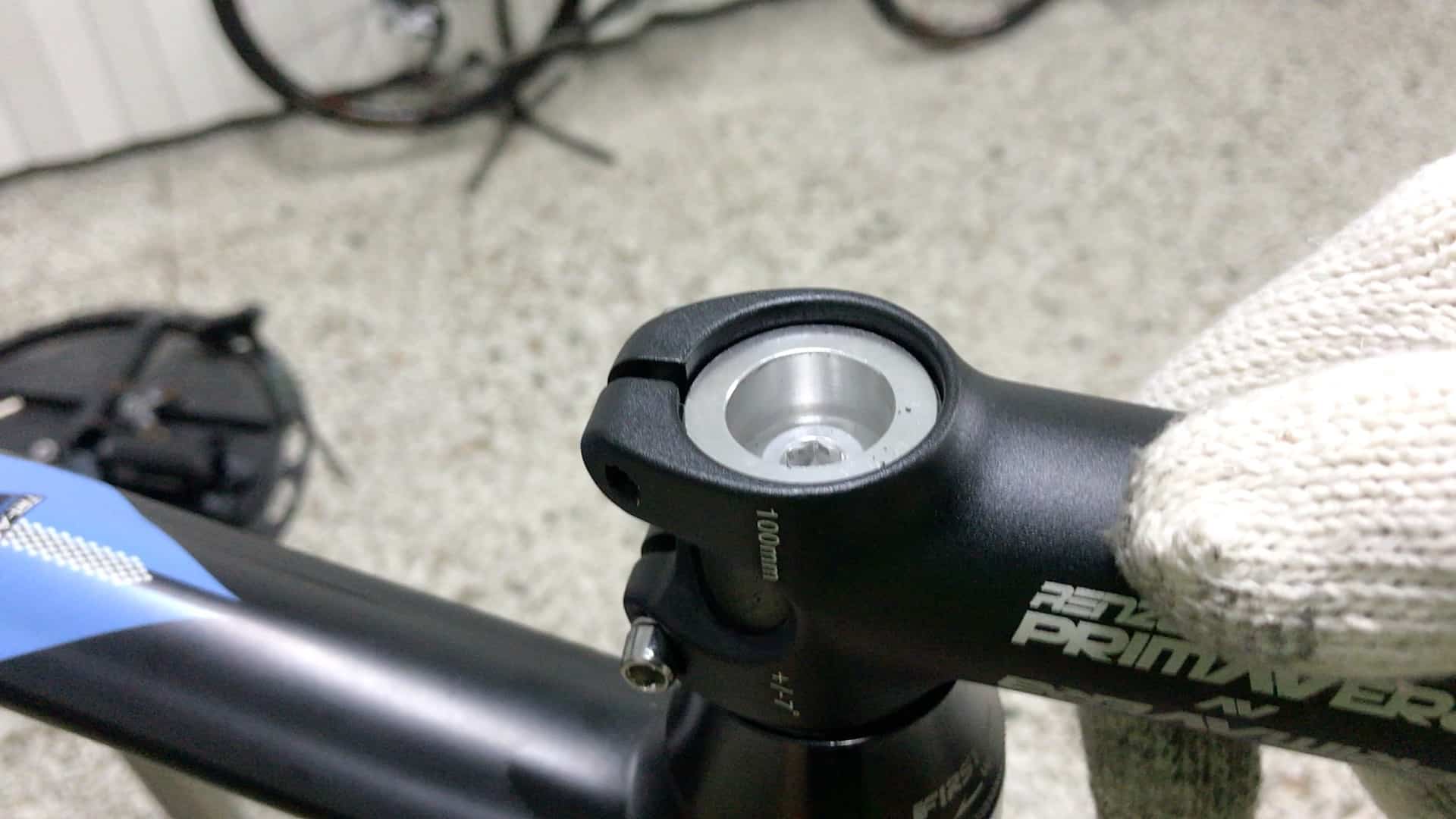
Slot the stem into position down the steerer.
If you’ve cut the fork correctly, you’ll see the gap between the top of the steerer, or the expander for a carbon frame.
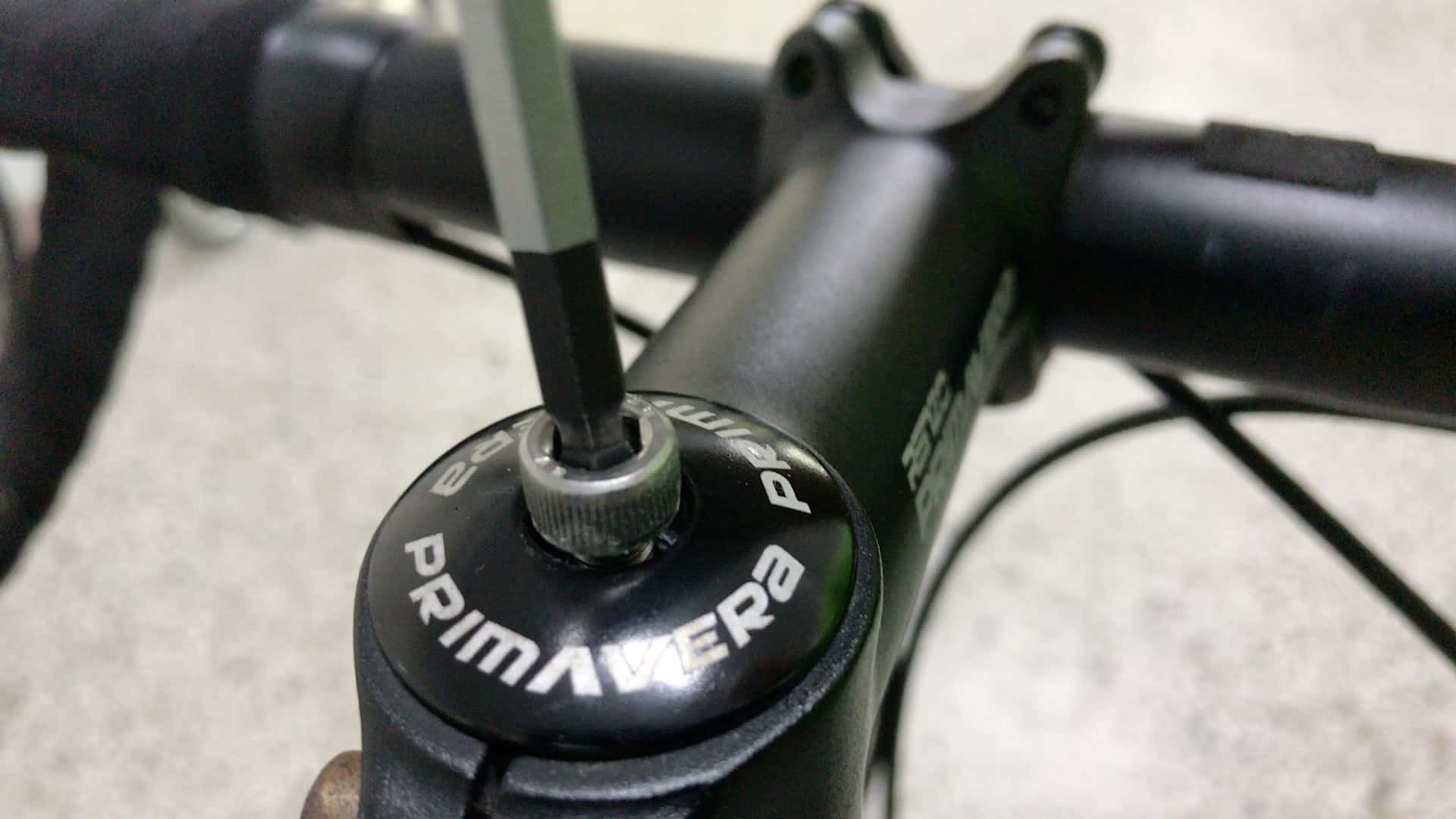
Install and tighten the compression bolt.
Again, if you’ve cut the fork correctly and the gap is sufficient, a light turn of the compression bolt as it fits down into the top cap will pull the fork assemblage together snug as a bug.
Tighten the stem bolt(s) enough to prevent the bars from sliding left or right.
Wait until the final bolt tightening procedure at the end of the build (tightening all bolts to tolerance with a torque wrench) to align the stem and handlebars square to the front wheel and tighten the bolts to the correct torque.
Front Brake
Disk brakes: install onto fork blade and the rear mount.
Caliper brakes: push the bolt into the rear of the fork, then turn the brake unit until flush with the fork.
7. HANDLEBARS, SHIFTERS, CABLE HOUSING and CABLES (Tuning Deraillers)
In this stage you:
- Install the handlebars
- Slide the shifters into the correct position
- Measure and cut the cable housings
- Install the brake and derailleur cables (or just brakes if the bike has electronic shifting)
Handlebars
If you’ve got an integrated stem and handlebar system, move on to #8
Otherwise, install the handlebars by
- removing the four stem faceplate bolts
- positioning the handlebar against the stem
- installing 2 of the bolts on opposite diagonals (top left, bottom right or vice versa)
- tightening those two enough to hold the handlebar then install the other bolts
Position the Shifters
Determining the exact position of the shifters is a matter of personal preference within practical limits.
Road bike shifters
It’s recommended you position the tips of the brake levers level with the tips of the drops.
Take your main bearing from the position of the hoods: you want them at least level with the plane of the handlebars that extends horizontally forward of the bars, although many cyclists prefer their shifters to project up at angle, often a very steep angle.
Bottom line, it’s a personal thing within the limits of shifters sitting either too low or too high.
Mountain bike (type) shifters
Measure how far grips you intend to install on the bars extend along the bars, left and right—that will be the shifter clamp’s position on each side.
The recommended angle is 45 degrees. Again, it’s personal. The shifter angle can be anything that works for whoever rides the bike, and can be adjusted, of course, for each rider.
Brake Levers or Master Cylinder
Bolt your brake levers for mechanical disk or caliper/cantilever brakes, and the master cylinder if you’re installing hydraulic disk brakes, to the handlebars.
Cable Housing
Cable housings are 5mm in diameter and are available in bike shops.
Measuring the cable housing with reference to the shifters without the cables installed. Measure and cut the cable housings first, install the cables, then finish off by installing the cables. Grease the cables, then slip the housings onto them and into position.
IMAGE – cable end caps
In most cases you need to slip a cable end cap, a ferrule, onto each cut end of a cable housing in order for it to fit into a component.
Some manufacturers don’t require this: Shimano and SRAM on some brakes and shifters for example.
NOTE: It’s best to use a dedicated cable housing cutting tool than a big pair of pliers or something similar. This tool is also necessary for cutting cables at the very end of the build.
This video clip demonstrates measuring and cutting cable housings with the cable housing tool.
Tuning the Derailleurs
The front derailleur is the trickiest. See the section on Deraillers above.
The rear derailleur is easier.
The key is to pull the cable as tight as you can before tightening the bolt onto the cable.
Shifting problems are nearly always a result of the cable being too loose; you may have to release the bolt and re-tighten the cable once or twice to get the gears running smoothly.
A common problem is not getting the chain to mount the largest cog (the smallest gear). That is 99.9% due to a cable that is too loose.
Turn the barrel adjuster as necessary where the chain runs rough on a particular cog as you run up and down through the gears.
8. BAR TAPE or GRIPS
For a building a standard road bike, you’ll be looking to tape the (drop-style) handlebars. Other types of bikes have some sort of version of a flat or riser bar and so take grips.
Wrapping Tape
Wrapping handlebar tape is a skill learned over time.
If you’ve got time to practice, then the more you do the better you will get.
Otherwise, get a bike shop pro to do it.
The technique depends on
- laying each layer one-half to one-third on the previous layer
- achieving the right amount of tension: not too loose and not to tight (you’ll snap the tape).
This video clip shows wrapping tape on a recumbent bike. The principles are the same however.
Installing Grips
Most have a clamp at the bar end, loosened and tightened with a 3mm Allen wrench.
Those that do not can be forced into position using soap and water—the water evaporates with the soap residue preserving a firm non-slip surface against the handlebars.
Or a jet of air generated by an air compressor for powering tools and other jobs around the house.
It takes less than a minute to slide a grip into position by delivering quick blasts of air from the nozzle inserted between the bar and the shifter whilst pushing at the same time.
9. SEAT POST and SADDLE
Bolting the saddle to the seat post before inserting the seat post into the seat tube is easiest.
To determine the correct seat height, the rider should take a 4mm or 5mm Allen wrench on every ride (multitools have a range of useful Allen keys built in).
You adjust the height as you go.
The recommended position is for a cyclist’s leg to form no less than a 90 degree angle at the top of a pedal stroke. That works for many cyclists. A 75-80 degree angle also works for many.
Once you’ve determined the most comfortable height, make a note with reference to the calibration marks most manufacturers print vertically along the rear of the seat post.
Here are two ways to help you get the initial seat height right for yourself or whoever will ride the bike.
Fist level with top of stem
Make a fist, turn it sideways, then place it on the seat. Align the top of the fist with the top of the stem.
Top of saddle level with hip
Raise or lower the seat post until the seat aligns with the cyclist’s hip.
10. TIGHTEN BOLTS to TORQUE TOLERANCE and CUT CABLES
Avoiding building a bike that’s not safe to ride is the goal.
As long as the frame and fork is good quality, and the components in good condition, AND the bolts are tight—but not too tight—you will achieve that goal.
Tightening all bolts to torque tolerance as the very last step in building a bike confirms that all the key bolts will be tightened to tolerance before it is ridden.
The following notes will guide you in the absence of specific manufacturer information on a component—always follow manufacturer’s guidelines where they exist.
Handlebars and Stem
Handlebar faceplate bolts: 4 Nm (Nm = Newton Meters).
Stem bolts: 4-5 Nm (each if 2 bolts); 6-8 Nm if a single bolt.
Shifter clamps: Flat bar 2-3 Nm; Road 5 Nm
Periodically check these bolts!
NOTE: keeping road shifters looser is sometimes recommended since in a crash the clamp bracket slides around the bar preventing it from breaking completely as it might if unable to move at all (ie. a 5 Nm of torque).
Derailleur Bolts
Front Derailleur
Seat tube clamp: 3-4 Nm
Derailleur bolt: 5 Nm
Cable bolt: 5-7 Nm
Rear Derailleur
Derailleur hanger bolt: 5 Nm
Cable bolt: 5-7 Nm
Brakes
Cable bolts front and back: 5-7 Nm
Disk brake caliper brackets: 5-7 Nm
Other Bolts
Seat post to seat clamp: crank it up tight 10 Nm+
Seat post clamp: 8-10 Nm
For complete information across a range of manufacturers, refer to Zinn and the Art of Mountain Bike or Zinn and the Art of Road Bike Maintenance: he includes a detailed guide to torque specifications as an appendix.
Cable Cutting
This video clip demonstrates cable cutting and crimping on the end caps.
FINAL REMARKS
If you are building a bike for the first time, prepare for it to take a little while.
You need to develop a degree of skill in specific techniques, particularly in handling the tools and getting a ‘feel’ for what’s right.
Here’s the whole process in a little over two minutes, more or less following the sequence of steps above, just lacking tape wrapping.
Good luck on your bike building adventure.