CNC is a cornerstone technology for creating bike components. So are hydraulic presses.
In this post, I’ll give you a look at how the bike industry makes most of the components on your bike.
I’ll mainly focus on CNC milling then CNC turning, the two modes of CNC machining that companies rely on for their component production.
Then I’ll look at how we make spindles for cartridge bottom brackets and our BMX regular bottom bracket sets.
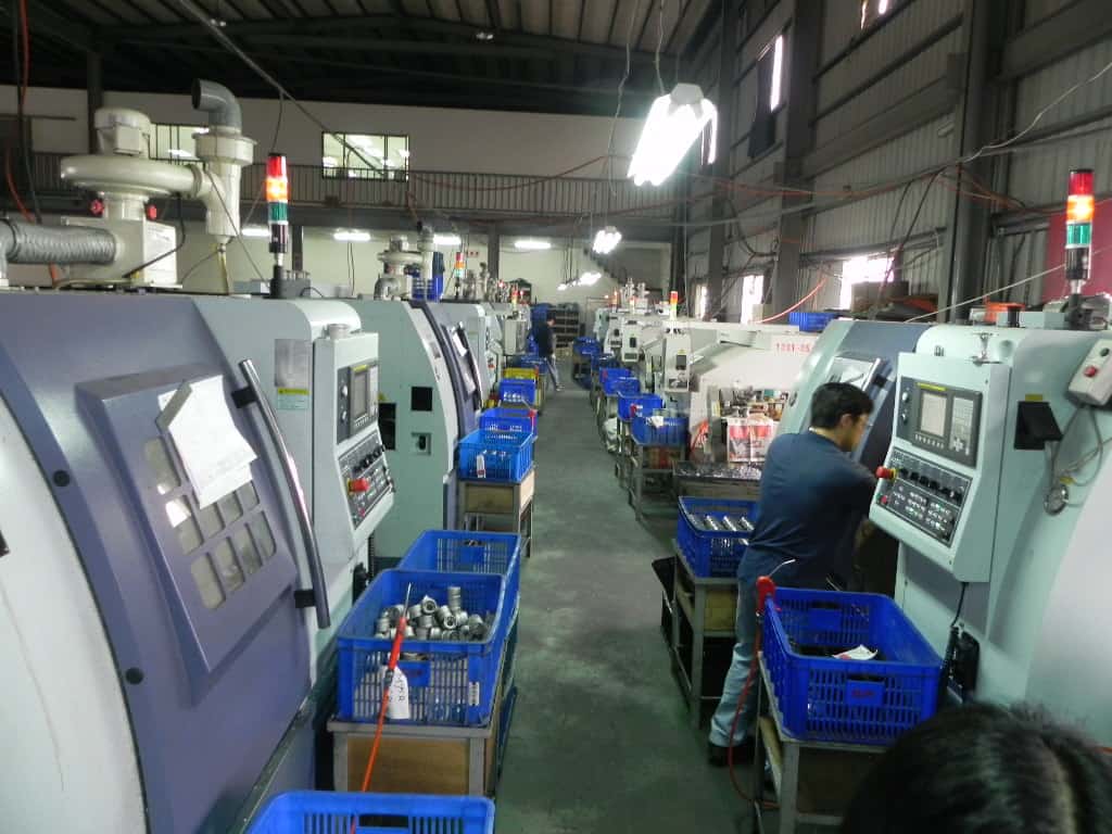
Poke your head into any CNC factory in Taiwan and you’ll see rows of CNC machines, although maybe not as many as above because this particular facility is one of the biggest.
A line of paired CNC machines is the standard way to set up a CNC shop.
Pairing makes operating the machines and processing jobs more efficient—one operator can handle two machines easily.
The operator places the piece to be milled in the machine. He then starts the sequence which takes a few minutes to complete.
While the machine executes the program, the operator turns to the other machine, removes a completed piece, replaces it with an unprocessed component, then begins the sequence for that piece.
A day’s machining involves this continual back and forth between two—or often amongst several—machines.
(Check out our extended review of bike crank arm manufacturing which involves an extended element of CNC machining).
CNC MILLING vs CNC TURNING
CNC milling refers to milling with a wide variety of tool bits. The piece or component being shaped remains in one position.
A rapidly rotating cylindrical tool bit, or milling cutter, moves over and around the piece removing material in accordance with the machine’s program.
The tool bit superficially resembles a traditional drillbit. However, a drill can only achieve a single axis motion, limiting its overall production capability. Milling cutters move along multiple axes allowing the designing engineer to create a diverse assortment of shapes, slots, and holes.
The machined piece in CNC turning, on the other hand, rotates rapidly. The cutting tool bits don’t move but are brought into contact with the piece to perform their cutting action.
One machine can complete several different operations on the one piece since several tools can be slotted into a platform that rotates around to the next tool when one cutting process is complete.
CNC milling and turning are exhaustively accurate with tolerances in the thousands of a millimeter. Companies are able to produce large batches of uniform components quickly and cost-effectively.
Small batches are also not prohibitively expensive to produce. CNC milling does not require molds or jigs, so small MOQs are economically viable.
CNC Milling
At First Components CNC milling is a key pillar in our manufacturing. But it’s not the only one. We use a variety of machinery to produce our range of bottom brackets, headsets, and cranksets.
We’ll explore our experience of CNC milling through chainring manufacture.
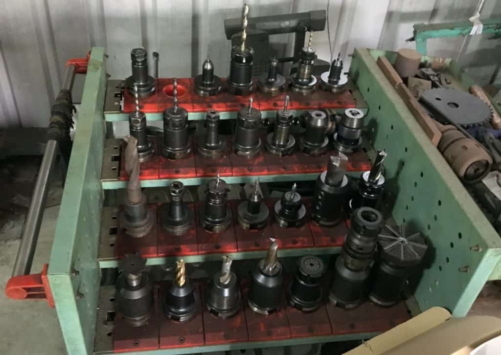
A small sample of the range of milling bits we use on the wide variety of pieces we machine. The only limits to what can be created are the practical use to which the products will be put.
Tool bits are generally high strength steel (HSS) or carbide-tipped for extra hardness.
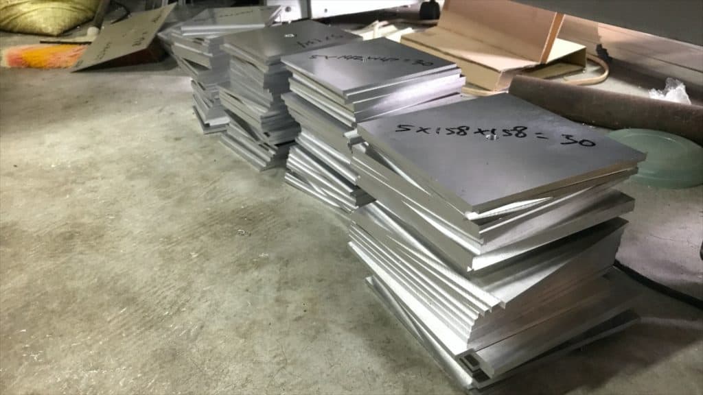
Aluminum blocks, or blanks, is the place to start with CNC chainring milling. Each blank is a little bigger than the final machined diameter, as measured from the apex of one chainring tooth to the tooth diametrically opposite. These blanks are the raw material for a variety of chainring shapes and sizes for a regular customer.
AL6061 and AL7005/75 are the types of aluminum alloy mostly used in bicycle component manufacturing.
Both are commonly referred to as “aerospace” aluminum, but AL6061 is a little heavier and therefore cheaper than AL7005. AL7046 is sometimes used since it’s 80% stronger than AL7005 and 16% lighter. Costing almost twice as much, though, the minimal advantage gained substituting it for the standard forms of aluminum is not justified.
At First Components we mainly use AL6061, although we make some cranks with AL7050 or AL6066. Our chainrings are exclusively made from AL7075.
CNC Turning
Turning involves fixing a blank on a platform or drum that holds a number of drill bits.
Fixed inside the CNC cabinet the piece rotates while the cutting tools remove material according to the specifications.
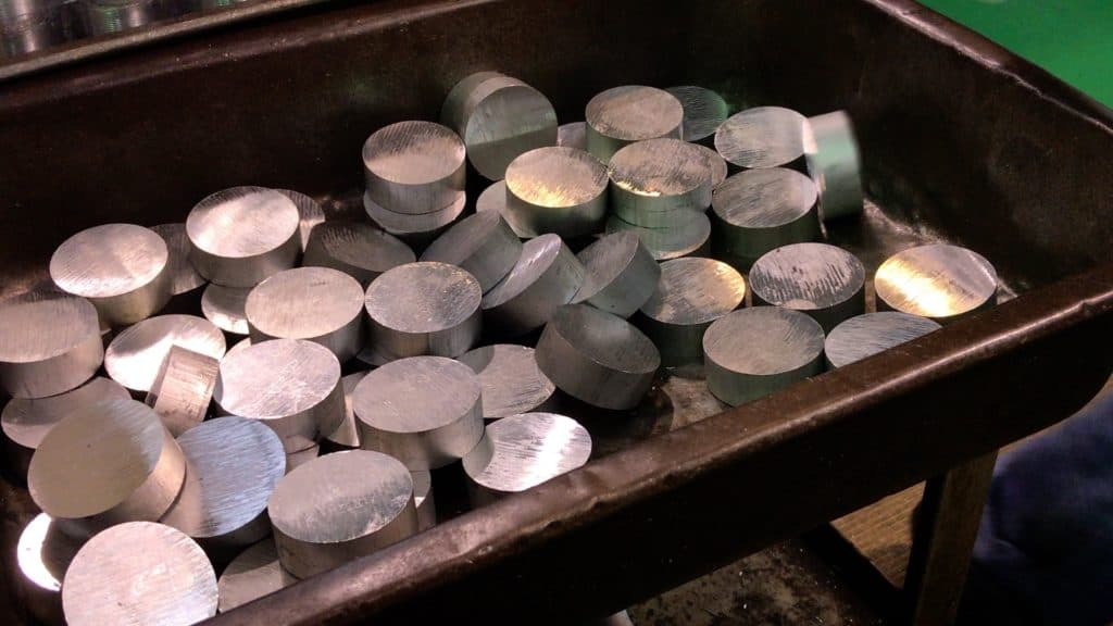
This is a batch of parts for our SRAM DUB bottom bracket tool.
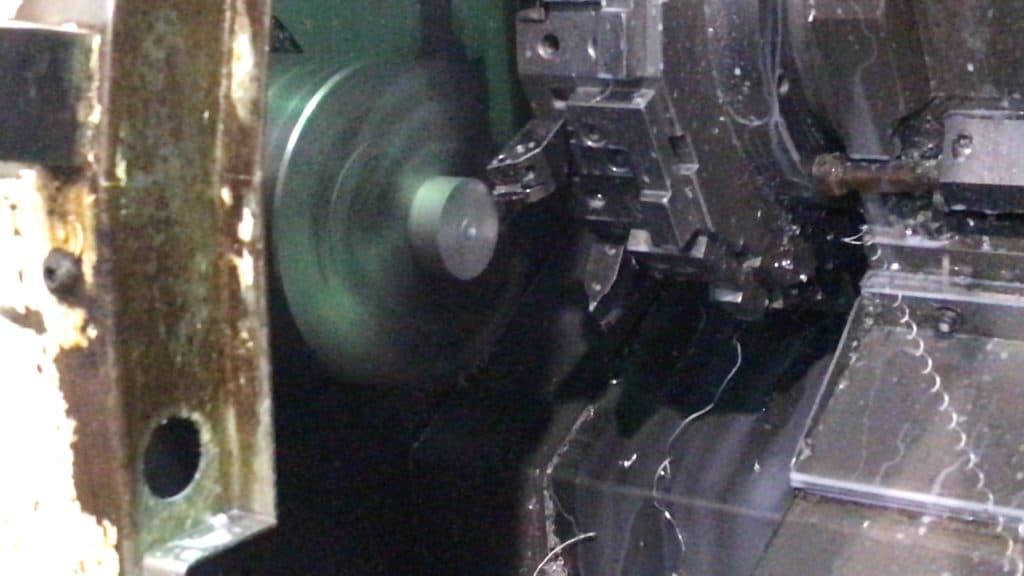
Fixed in position, the blank rotates at high speed. Two tool bits work on the piece in succession.
The first tool cuts the center. Once that cutting is complete, the drum upon which it is mounted rotates to the next tool bit which removes alloy from the outer edge to the inside.
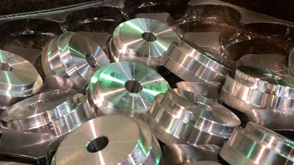
The final result is the batch of cleanly machined pieces. The next step is anodizing and finishing off.
CNC MILLING NARROW-WIDE CHAINRINGS
We’ll look at the whole CNC process by one of three CNC milling units in the First Components chainring processing workshop.
The operator slides the doors closed having fixed the blanks into position. CNC milling machines have either the one sliding door or two, as with the machine we rely on for machining chainrings. Closing the doors prevents swarf being flung into the workshop.
Most CNC milling processes require liberal quantities of coolant directed at the point of contact between tool bit and the metal surface being milled. Closing the doors is a must in those circumstances.
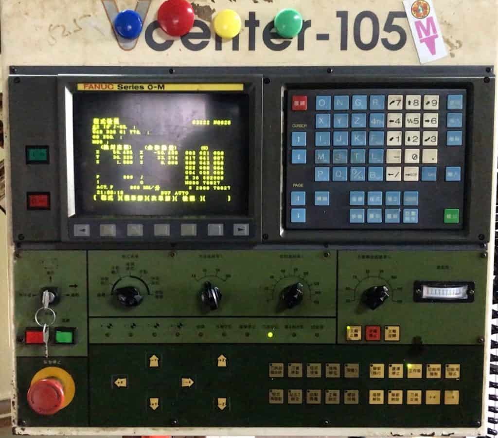
The operating unit is usually located on the right side. The most prominent feature is the start/stop button, as with most machinery utilizing high-speed processing.
The operator normally only needs to hit the start button—once the sequence completes, the unit shuts down automatically. Otherwise, the only reason to hit the button is for an emergency stop.
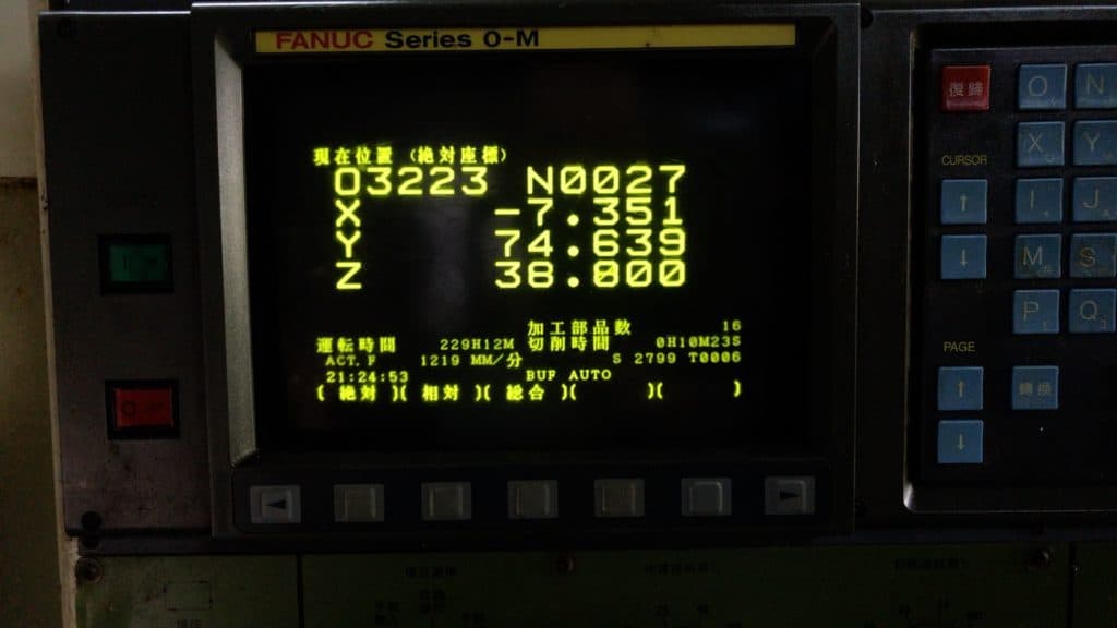
The CNC program controls the cutter head position via XYZ coordinates. “X” and “Y” determine the horizontal position on the positive and negative X & Y axes—imagine a bird’s eye view looking down from directly above. The “Z” value determines vertical position.
The following example covers the process for milling the narrow-wide chainring portion of a recent production for a regular customer.
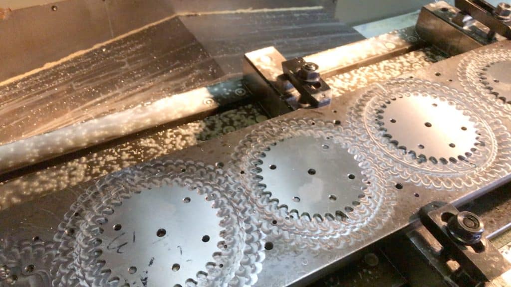
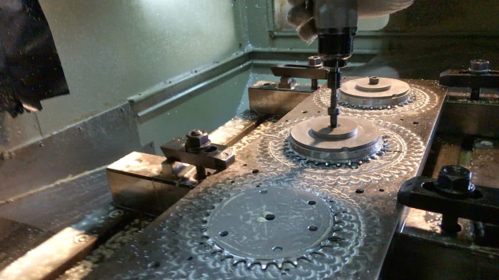
The chainring teeth have already been cut so all teeth are the same shape and thickness. The CNC milling task now is to cut a narrow-wide profile into the teeth.
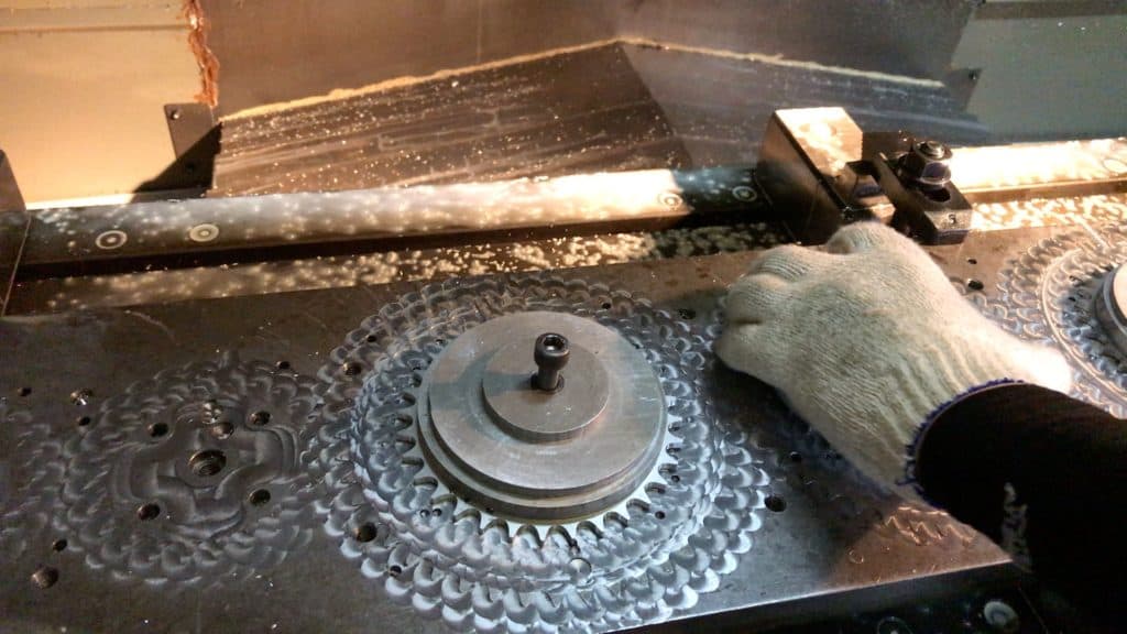
The base plate contains four mounts. The operator places one chainring on each, positions the holding plate over the top, then bolts it securely.
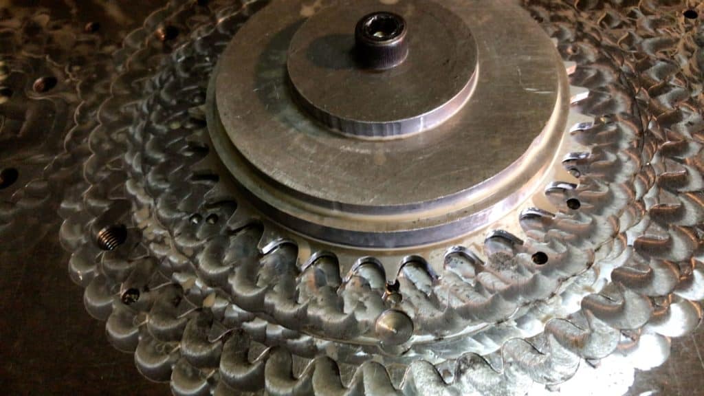
The plate holds the chainring firmly in position for the CNC milling tool bit which moves clockwise, milling each tooth to specification.
Once the operator hits the big red button starting the sequence, the platform upon which the plates are mounted moves into the center of the cabinet. The tool module descends. The cutting sequence is from right to left.
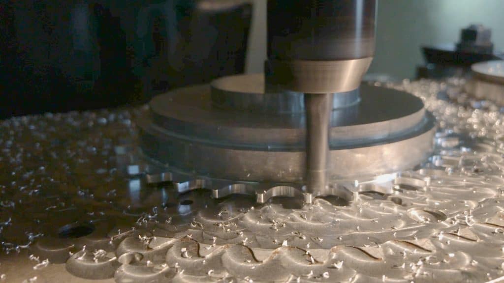
Each chainring is milled in turn. The tool bit cuts through the inside of two teeth removing most material from the middle tooth making it the narrow tooth in the alternating profile of wide-narrow-wide-narrow.
The milling complete, the operator unbolts the plates, removes the chainrings, replaces them with a new batch repeating the process until the batch is done.
FROM CNC MILLING to the BOTTOM BRACKET SPINDLE HYDRAULIC PRESS
CNC Milling is one of our production processes and how we make chainrings.
We also require different forms of processing and thus different equipment for our headsets and bottom brackets.
We employ several specialized machines for headset and bottom bracket processing. CNC machining is not a solution for headset and bottom bracket machining requirements.
There is consistent demand for cottered spindles and square taper spindles, so we’ll take their manufacturing process as our example.
Square taper spindles can stand alone—our BMX regular BB set for instance. Or they are integrated into the ever-popular square taper cartridge bottom bracket.
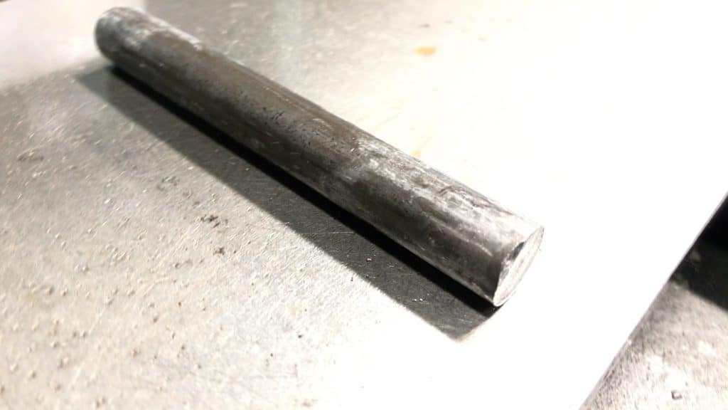
Every spindle begins life as a blank.
You can probably see this piece fixed in a CNC machine for milling or lathe processing in your mind’s eye. Shaping a blank in that way would require carbide-tipped cutters—too expensive and not durable enough for the number of spindles it has to get through.
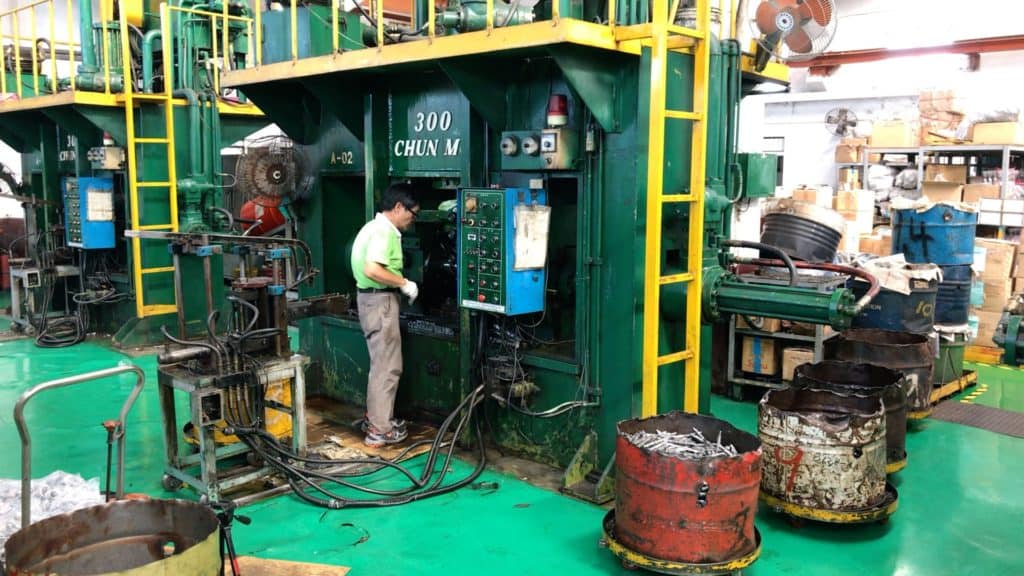
The better, standard, alternative is a very large hydraulic press. We have two on the floor to cope with large orders during times of high demand.
Here’s how the press works.
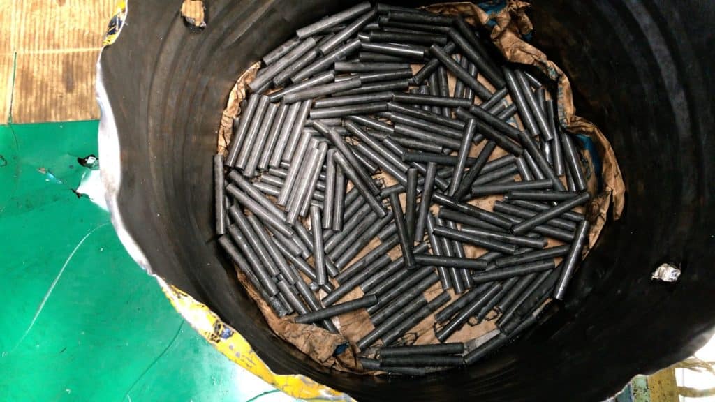
We process them by the barrel … getting close to the bottom here.
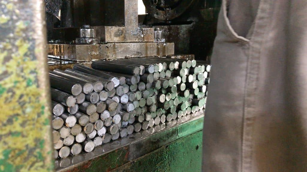
The operator arranges the blanks in a row right in front of the press forge.
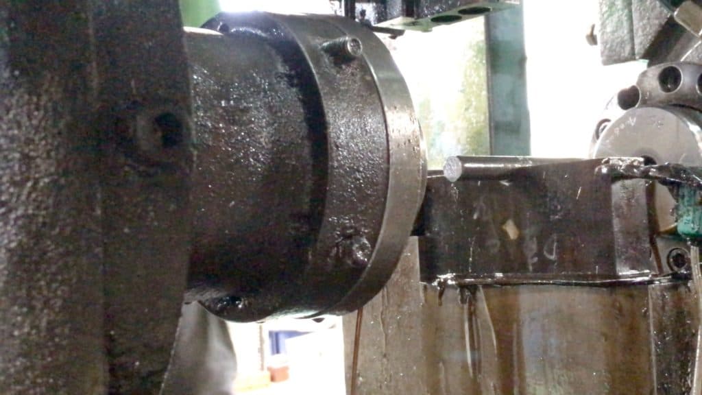
He places each blank on the forge, creating a complete spindle in two movements.
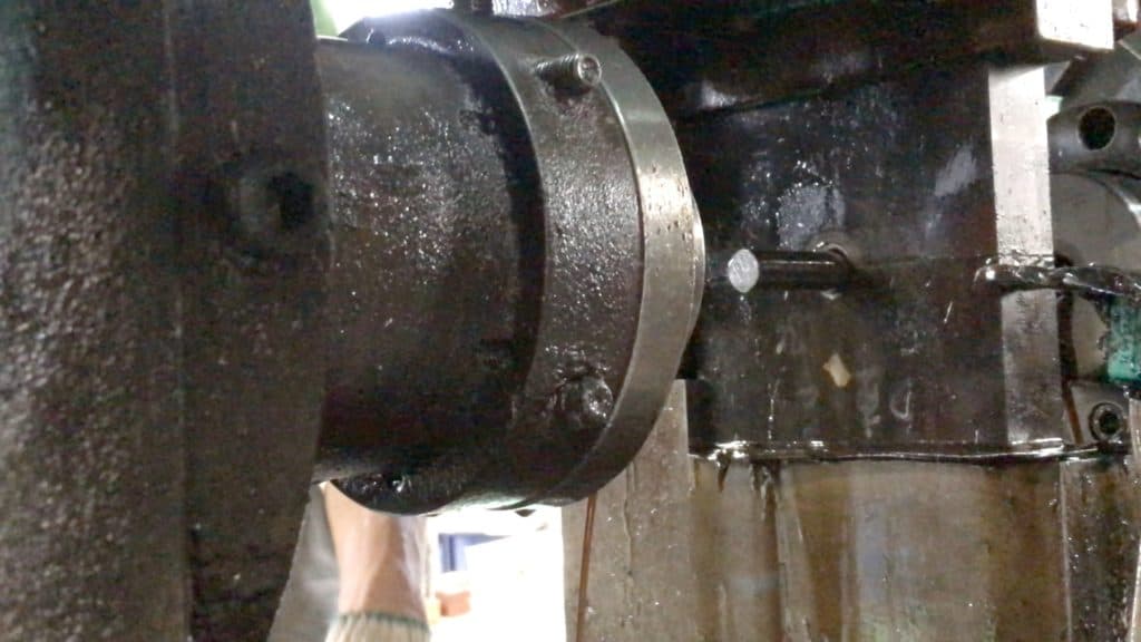
The vertical movement shapes the section that sits inside the BB shell and holds the spindle ready for the lateral press.
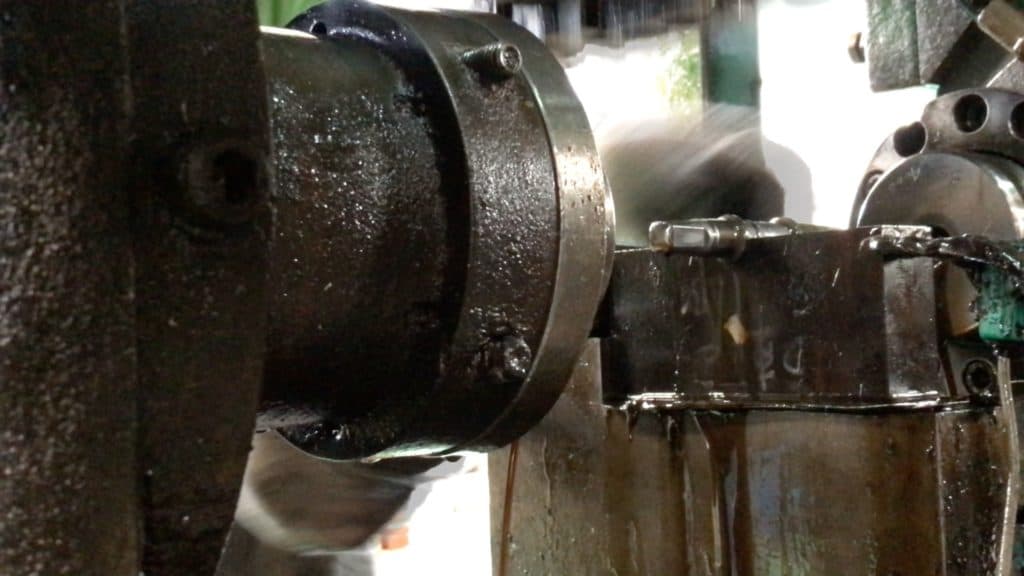
The lateral press moves in simultaneously from the left and right, creating the distinctive four-faced square taper profile.
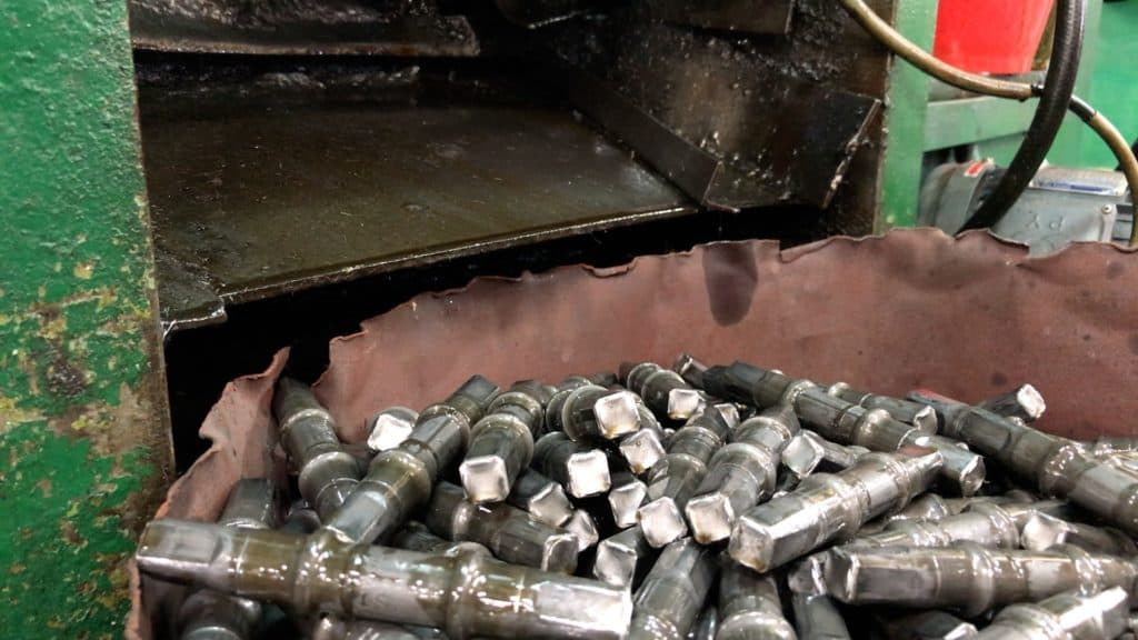
The operator slides the completed spindle into a collection bin at the back of the press.
Regular random testing of units from the batch is the way to pick up any processing deficiencies in the midst of production, rather than get to the end and find the hydraulic press strayed from within acceptable tolerances.
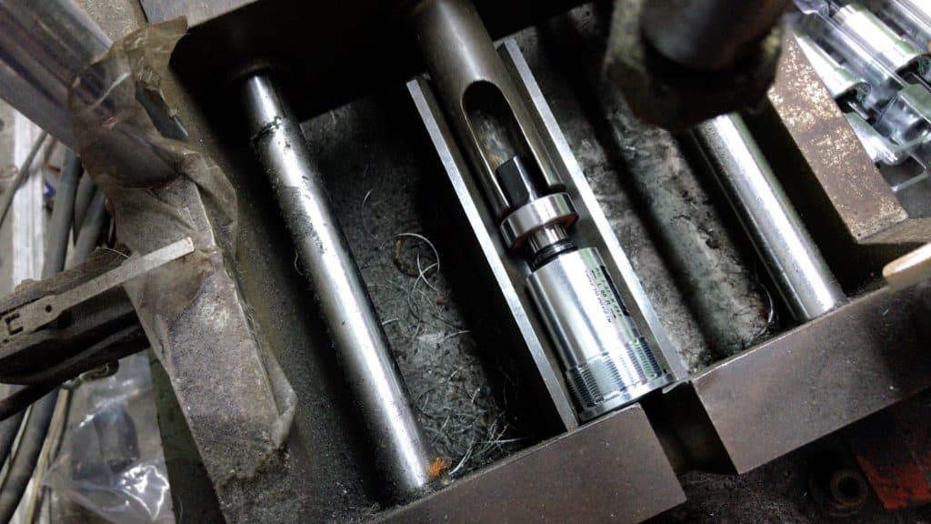
He first checks the square taper ends to ensure they will fit the intended bike crank (arm).
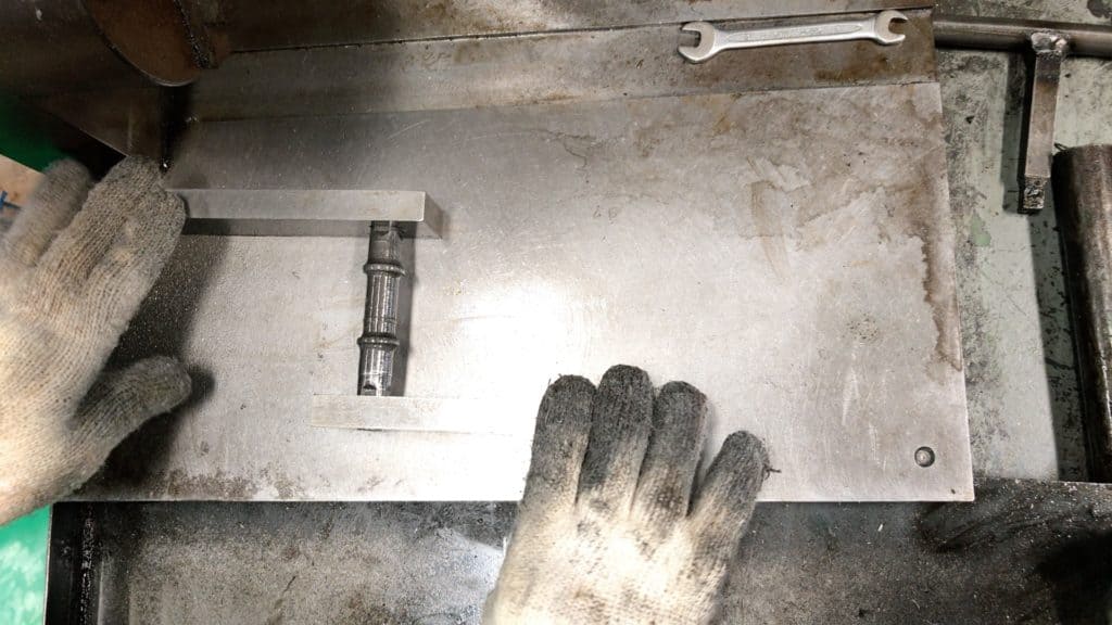
That’s a snug fit for both the left and right.
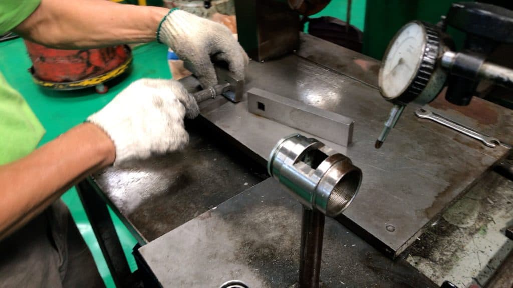
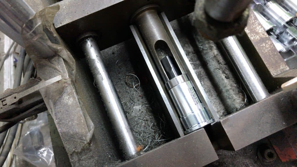
The second test simulates the spindle rotating with the bearings.
The cylinder slipped over the end is perfectly symmetrical. The micrometer displays any deviation beyond acceptable tolerances as the operator rotates the spindle.
CARTRIDGE BOTTOM BRACKET ASSEMBLY
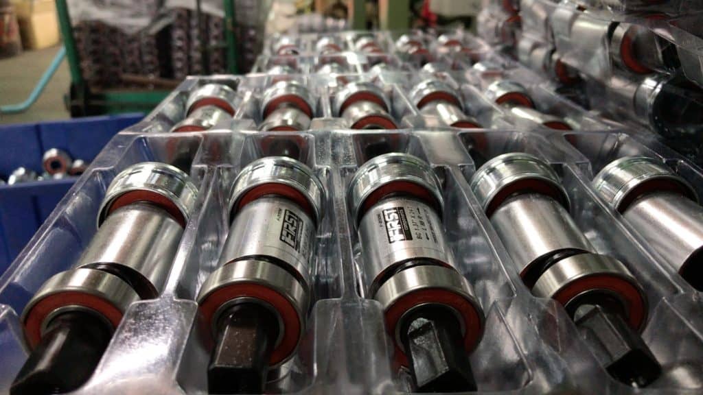
Here’s a batch of cartridge bearings ready to assemble.
The drive side bearing, spindle and non-drive side are loosely arranged together in the packing tray.
The goal is to simultaneously press the drive side and non-drive side sealed bearings into the cartridge body with the spindle firmly fixed through the middle.
The components rest at an angle in the press. The non-drive side, sealed bearing, sits at the lowest point.
The cartridge body sits a few millimeters inside the bearing. The spindle runs inside each component with the drive-side bearing on the top.
The piston presses the drive side bearing into the cartridge body as the cartridge body presses into the non-drive side sealed bearing.
BOTTOM BRACKET TESTING
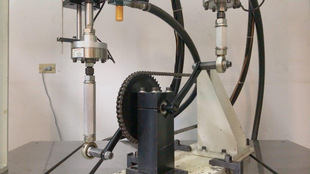
Here we have the bottom bracket torture machine.
Its testing procedure stresses left and right sealed bearings under conditions much more severe than ever encountered on the road or even the trail.
The testing unit does not rotate the cranks. The attached piston arms exert 180 kg force on an upstroke on one side, which is also an upstroke on the other side.
Road bikes are tested at an angle of 45° 100,000 times. Mountain bikes are tested at 45° for 50,000 times, and at 30° for 50,000 times, a total of 100,000.
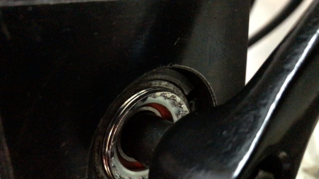
Each bearing’s race is pulled violently in one direction, then just as violently in the other.
You’ll see the race squashed against the spindle in the image. When the piston pulls the crank back down, the spindle squashes against the race’s lower section.
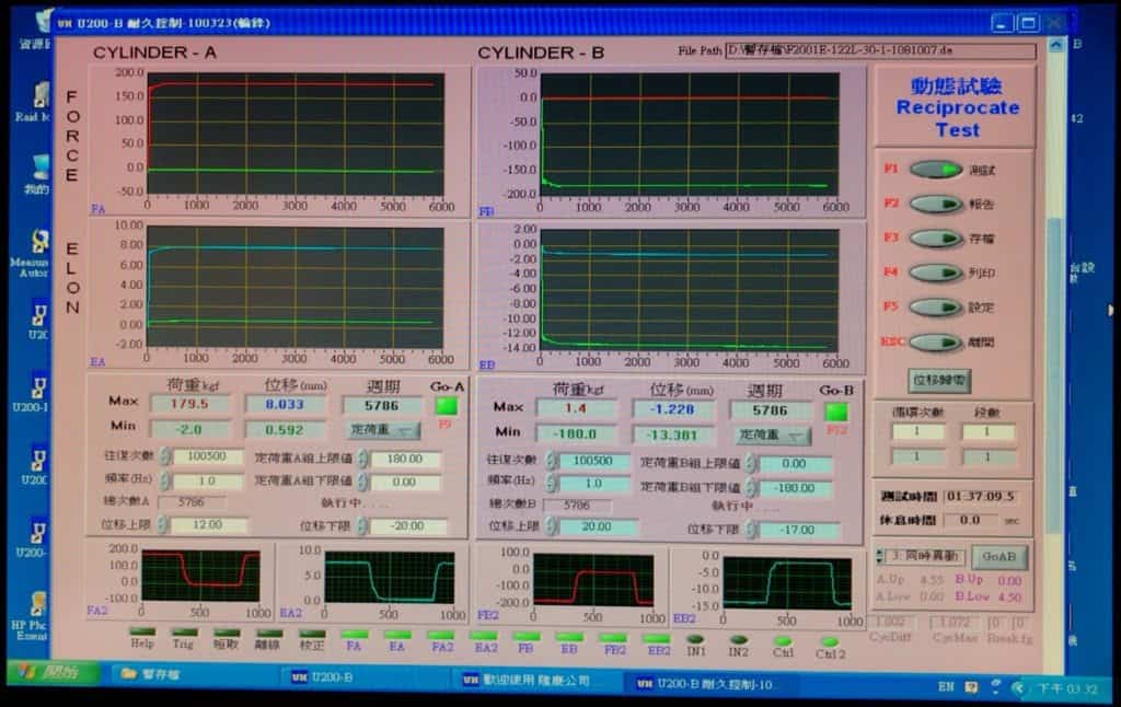
The computer monitors each moment of the test, with the data output continuously recorded for output in an official record of the test.
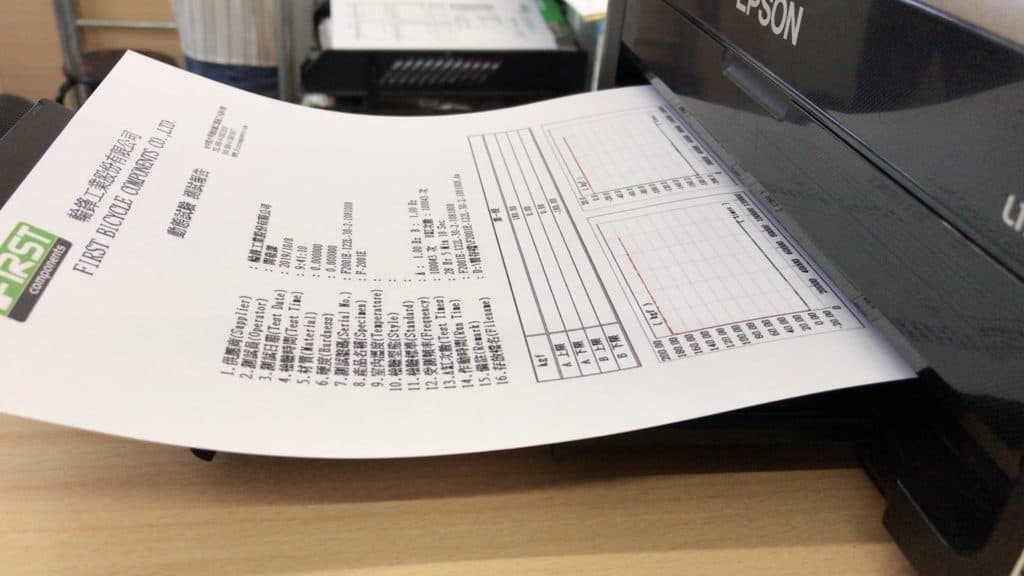
Parameters and results are aggregated into a summary for the duration of the test.
FINAL COMMENTS
So there you have a brief glimpse of how we go about some of our manufacturing processes. Our product range requires several other specialist machines that we’ll cover in separate articles later.
In the bicycle industry and manufacturing industry generally speaking, CNC milling and CNC turning are foundational processes. A CNC machine makes component processing quick and efficient. A factory can also generally accommodate customers with smaller orders.
What does the future look like? More CNC processing than ever before.
However additive manufacturing is becoming increasingly sophisticated and offers a complementary manufacturing mode. Largely confined to rapid prototype production, 3D printing, as it is more commonly known, is moving into complex manufacturing which includes bike frames.
CNC milling and turning together with 3D printing looks set to dominate the future.